Gigabyte GA8PE800 User Guide - Page 31
F_ USB1 / F_USB2Front USB Connector, Yellow, CI CASE OPEN
 |
View all Gigabyte GA8PE800 manuals
Add to My Manuals
Save this manual to your list of manuals |
Page 31 highlights
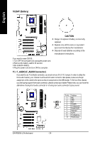
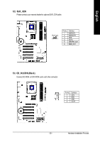
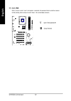
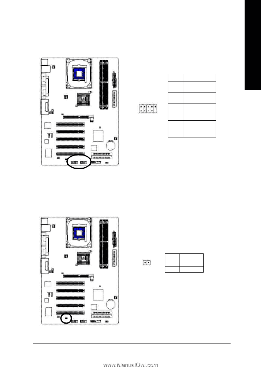
English 16) F_ USB1 / F_USB2(Front USB Connector, Yellow) Be careful with the polarity of the front USB connector. Check the pin assignment while you connect the front USB cable. Please contact your nearest dealer for optional front USB cable. 2 10 19 Pin No. 1 2 3 4 5 6 7 8 9 10 Definition Power Power USB DXUSB DyUSB DX+ USB Dy+ GND GND No Pin NC 17) CI (CASE OPEN) This 2 pin connector allows your system to enable or disable the "case open" item in BIOS if the system case begin remove. PinNo. Definition 1 1 Signal 2 GND - 27 - Hardware Installation Process
-
 1
1 -
2
-
3
-
4
-
5
-
6
-
7
-
8
-
9
-
10
-
11
-
12
-
13
-
14
-
15
-
16
-
17
-
18
-
19
-
20
-
21
-
22
-
23
-
24
-
25
-
 26
26 -
 27
27 -
 28
28 -
 29
29 -
 30
30 -
 31
31 -
 32
32 -
 33
33 -
 34
34 -
 35
35 -
 36
36 -
37
-
38
-
39
-
40
-
41
-
42
-
43
-
44
-
45
-
46
-
47
-
48
-
49
-
50
-
51
-
52
-
53
-
54
-
55
-
56
-
57
-
58
-
59
-
60
-
61
-
62
-
63
-
64
-
65
-
66
-
67
-
68
-
69
-
70
-
71
-
72
-
73
-
74
-
75
-
76
-
77
-
78
-
79
-
80
-
81
-
82
-
83
-
84
-
85
-
86
-
87
-
88
-
89
-
90
-
91
-
92
-
93
-
94
-
95
-
96
 |
 |
- 27 -
Hardware Installation Process
English
16)
F_ USB1 / F_USB2(Front USB Connector, Yellow)
Be careful with the polarity of the front USB connector. Check the pin assignment while you connect
the front USB cable. Please contact your nearest dealer for optional front USB cable.
17)
CI (CASE OPEN)
This 2 pin connector allows your system to enable or disable the "case open" item in BIOS
if the system case begin remove.
2
10
1
9
Pin No.
Definition
1
Power
2
Power
3
USB DX-
4
USB Dy-
5
USB DX+
6
USB Dy+
7
GND
8
GND
9
No Pin
10
NC
1
Pin No.
Definition
1
Signal
2
GND