Harman Kardon AVR 1710 Owners Manual - Page 7
Rear-Panel Connectors, continued - avr analog audio output
 |
View all Harman Kardon AVR 1710 manuals
Add to My Manuals
Save this manual to your list of manuals |
Page 7 highlights
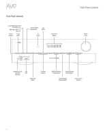
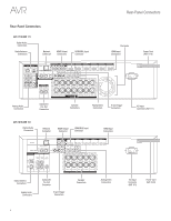
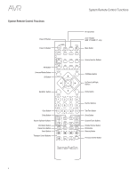
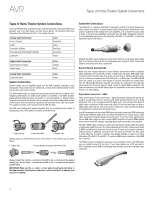
English AVR Rear-Panel Connectors Rear-Panel Connectors, continued Digital Audio connectors: If your non-HDMI source devices have digital outputs, connect them to the AVR's digital audio connectors. NOTE: Make only one type of digital connection (HDMI, optical or coaxial) from each device. See Connect Your Audio and Video Source Devices, on page 16, for more information. Radio Antenna connectors: Connect the supplied AM and FM antennas to their respective terminals for radio reception. Analog Audio connectors: The following analog audio connectors are provided: • Analog Audio Input connectors: Use the AVR's Analog Audio Input connectors for source devices that don't have HDMI or digital audio connectors. See Connect Your Audio and Video Source Devices, on page 16, for more information. • Zone 2 Out connectors (AVR 1710/AVR 171 only): Connect these jacks to an external amplifier to power the speakers in the remote zone of a multizone system. Network connector: If your home network is wired, use a Cat. 5 or Cat. 5E Ethernet cable (not supplied) to connect the AVR's Network connector to your home network to enjoy Internet radio and content from DLNA-compatible devices that are connected to the network. See Connect to Your Home Network, on page 18, for more information. Subwoofer Pre-Out connector: Connect this jack to a powered subwoofer with a linelevel input. See Connect Your Subwoofer, on page 15, for more information. NOTE: The AVR 1710 and AVR 171 have two subwoofer connectors. HDMI Output connectors: If your TV has an HDMI connector and you are connecting HDMI source devices to the AVR, use an HDMI cable (not included) to connect it to the AVR's HDMI Out connector. NOTE: The AVR 1710 and AVR 171 have two HDMI Out connectors. Notes on using the HDMI Output connector: • When connecting a DVI-equipped display to the HDMI Out connector, use an HDMI-to-DVI adapter and make a separate audio connection. • Make sure the HDMI-equipped display is HDCP (High-bandwidth Digital Content Protection)-compliant. If it isn't, do not connect it via an HDMI connection; use an analog video connection instead and make a separate audio connection. • AVR 1710/AVR 171 only: If you have connected a 3D-capable TV to HDMI Out 1 and a 2D-capable TV to HDMI Out 2, the AVR will not allow 3D playback when both TVs are powered on. To watch 3D content, turn off the AVR and both TVs, then first turn on the 3D TV, then turn on the AVR, and finally turn on the 3D source device. Do NOT turn the 2D TV back on. HDMI® Input connectors: An HDMI connection transmits digital audio and video signals between devices. If your source devices have HDMI connectors, using them will provide the best possible video and audio performance quality. Since the HDMI cable carries both digital video and digital audio signals, you do not have to make any additional audio connections for devices you connect via the HDMI connection. See Connect Your Audio and Video Source Devices, on page 16, for more information. IR and Trigger connector: The following IR and trigger connectors are provided: • IR In connectors: When the IR sensor on the front panel is blocked (such as when the AVR is installed inside a cabinet), connect an optional IR receiver to the IR In jack. • 12V Trigger connector: This connector provides 12V DC whenever the AVR is on. It can be used to turn on and off other devices such as a powered subwoofer. • Zone 2 IR Input connector (AVR 1710/AVR 171 only): Connect a remote IR receiver located in Zone 2 of a multizone system to this jack to control the AVR from the remote zone. Fan Vents (AVR 1710/AVR 171 only): These vents are used by the AVR's fan to cool the system. Maintain a clearance of at least three inches (75mm) from the nearest surface to avoid overheating the unit. It is normal for the fan to remain off at most normal volume levels. An automatic temperature sensor turns the fan on only when it is needed. IMPORTANT NOTE: Never block the fan vents. Doing so could allow the AVR to overheat to dangerous levels. AC Input connector (AVR 171/AVR 161 only): After you have made and verified all other connections, plug the supplied AC power cord into this receptacle and into an unswitched wall outlet. Power cord (AVR 1710/AVR 1610 only): After you have made and verified all other connections, plug the power cord into an unswitched wall outlet. HDMI/MHL Input connector: If you have a Roku Streaming Stick or other MHL-capable device, connect it only to this HDMI/MHL In connector. If you do not have an MHL device you can use this connector for an HDMI-capable device. Speaker connectors: Use two-conductor speaker wire to connect each set of terminals to the correct speaker. See Connect Your Speakers, on page 14, for more information. NOTE: The Assigned Amp speaker connectors (AVR 1710/AVR 171 only) are used for the surround back or Front Height channels in a 7.1- channel home theater, or you can reassign them to a remote room for multizone operation or to front height channels for Dolby® Pro Logic IIz operation. See Place Your Speakers, on page 11, for more information. Analog Video connectors: The following Analog Video connectors are provided: • Composite Video Input connectors: Use composite video connectors for video source devices that don't have HDMI connectors. You will also need to make an audio connection from the source device to the AVR. See Connect Your Audio and Video Source Devices, on page 16, for more information. • Composite Video Monitor Out connector: If your TV or video display does not have an HDMI connector, or if your TV does have an HDMI connector but you are connecting some source devices with only composite video connectors, use a composite video cable (not included) to connect the AVR's Composite Video Monitor Out connector to your TV 's composite video input. 7
-
 1
1 -
 2
2 -
 3
3 -
 4
4 -
 5
5 -
 6
6 -
 7
7 -
 8
8 -
 9
9 -
 10
10 -
 11
11 -
 12
12 -
13
-
14
-
15
-
16
-
17
-
18
-
19
-
20
-
21
-
22
-
23
-
24
-
25
-
26
-
27
-
28
-
29
-
30
-
31
-
32
-
33
-
34
-
35
-
36
-
37
-
38
-
39
-
40
-
41
-
42
-
43
-
44
-
45
-
46
-
47
-
48
-
49
-
50
-
51
-
52
 |
 |