Hayward CAT 6000 CAT 6000 Owners Manual - Page 13
manufacturer's instructions at this time.
 |
View all Hayward CAT 6000 manuals
Add to My Manuals
Save this manual to your list of manuals |
Page 13 highlights
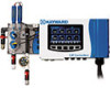
Note: For steps 9 and 10 refer to the "Typical CAT 6000 Installation Diagram" at the end of this document as well as Figure 6 below. Fig 6 9. Drill and tap a 1/4" NPT port at a location just down-stream of the filter, but up-stream from any chemical injection point. Install a tubing connector, and run flex tubing to the influent flow cell port. 10. Drill and tap a 1/4" NPT port at a location subject to vacuum or reduced pressure, such as a point upstream of the pump. Install the remaining tubing connector and run flex tubing to the effluent flow cell port. 11. If new or additional chemical feeders are to be used with the controller, install according to manufacturer's instructions at this time. 12. Power the unit using the power supply cord. 13. In order to minimize the time that the sensor is without power, disconnecting the chlorine sensor from the battery and reconnecting it to the unit should be done as quickly as possible. Disconnect the battery from the mounted sensor and immediately plug the sensor into the powered controller using the designated wire. 12 USE ONLY HAYWARD GENUINE REPLACEMENT PARTS
-
 1
1 -
2
-
3
-
4
-
5
-
6
-
7
-
 8
8 -
 9
9 -
 10
10 -
 11
11 -
 12
12 -
 13
13 -
 14
14 -
 15
15 -
 16
16 -
 17
17 -
 18
18 -
19
-
20
-
21
-
22
-
23
-
24
-
25
-
26
-
27
-
28
-
29
-
30
-
31
-
32
-
33
-
34
-
35
-
36
-
37
-
38
-
39
-
40
-
41
-
42
-
43
-
44
-
45
-
46
-
47
-
48
 |
 |
