Hayward CAT 6000 CAT 6000 Owners Manual - Page 7
Reattach the Flow Cell assembly
 |
View all Hayward CAT 6000 manuals
Add to My Manuals
Save this manual to your list of manuals |
Page 7 highlights
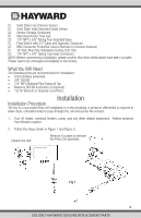
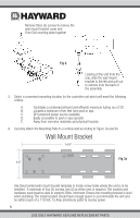
When the wall mount bracket is secured in location, attach the unit by aligning the tabs and slot on the back of the unit as when the wall mount bracket was removed in step 4. Slide the unit to the right to "lock" it into position. Fig 3b 5. Assemble the unit as described in Figure 4. Reattach the wall mount bracket cover and Flow Cell mounting plate to the wall mount bracket using the same three (3) screws from step 3. Fig 4 Reattach the Flow Cell assembly using the same four (4) screws from step 2. 6 USE ONLY HAYWARD GENUINE REPLACEMENT PARTS
-
 1
1 -
 2
2 -
 3
3 -
 4
4 -
 5
5 -
 6
6 -
 7
7 -
 8
8 -
 9
9 -
 10
10 -
 11
11 -
 12
12 -
13
-
14
-
15
-
16
-
17
-
18
-
19
-
20
-
21
-
22
-
23
-
24
-
25
-
26
-
27
-
28
-
29
-
30
-
31
-
32
-
33
-
34
-
35
-
36
-
37
-
38
-
39
-
40
-
41
-
42
-
43
-
44
-
45
-
46
-
47
-
48
 |
 |

USE ONLY HAYWARD GENUINE REPLACEMENT PARTS
6
5.
Assemble the unit as described in Figure 4.
When the wall mount bracket is secured
in location, attach the unit by aligning
the tabs and slot on the back of the unit
as when the wall mount bracket was
removed in step 4. Slide the unit to the
right to “lock” it into position.
Fig 3b
Reattach the wall mount bracket cover
and Flow Cell mounting plate to the
wall mount bracket using the same
three (3) screws from step 3.
Reattach the Flow Cell assembly
using the same four (4) screws
from step 2.
Fig 4