Hayward CAT 6000 CAT 6000 Owners Manual - Page 5
Installation
 |
View all Hayward CAT 6000 manuals
Add to My Manuals
Save this manual to your list of manuals |
Page 5 highlights
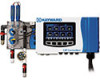
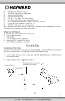
(1) Solid State Free Chlorine Sensor (1) Solid State Total Dissolved Solids Sensor (2) Sensor Storage Containers (1) Machined Acrylic Flow Cell (3) 1/4" NPT x 3/8" Tubing True-Seal Ball Valve (1) Flow Switch with 24" Cable and Specialty Connector (2) BNC Connector Protective Covers (Remove to Connect Sensors) (1) 30' Roll, Blue Poly Installation Tubing (3/8" OD) (2) 1/4" NPT x 3/8" Tubing True-Seal Connectors NOTE: Before commencing installation, please confirm that items listed above have been included. Please report any shortages immediately to the factory. What You Will Need The following tools are recommended for installation: • Drill (Cordless preferred) • 3/8" Drill Bit • 1/4" NPT (National Pipe Tapered) Tap • Masonry Drill Bit & Anchors (if required) • 13/16" Wrench or Channel-Lock Pliers. Installation Installation Procedure The key to a successful flow cell installation is in the plumbing. A pressure differential is required to allow clean, untreated water to pass through the cell and across the sensors. 1. Turn off heater, chemical feeders, pump, and any other related equipment. Relieve pressure from filtration system. 2. Follow the steps shown in Figure 1 and Figure 2. Unpack the unit. Remove 4 screws to remove the Flow Cell assembly. Fig 1 4 USE ONLY HAYWARD GENUINE REPLACEMENT PARTS
-
 1
1 -
 2
2 -
 3
3 -
 4
4 -
 5
5 -
 6
6 -
 7
7 -
 8
8 -
 9
9 -
 10
10 -
 11
11 -
12
-
13
-
14
-
15
-
16
-
17
-
18
-
19
-
20
-
21
-
22
-
23
-
24
-
25
-
26
-
27
-
28
-
29
-
30
-
31
-
32
-
33
-
34
-
35
-
36
-
37
-
38
-
39
-
40
-
41
-
42
-
43
-
44
-
45
-
46
-
47
-
48
 |
 |
