HealthRider Aire Strider E60 Elliptical English Manual - Page 8
Arm onto the left Upper Body Leg 31. Slide the Right
 |
View all HealthRider Aire Strider E60 Elliptical manuals
Add to My Manuals
Save this manual to your list of manuals |
Page 8 highlights
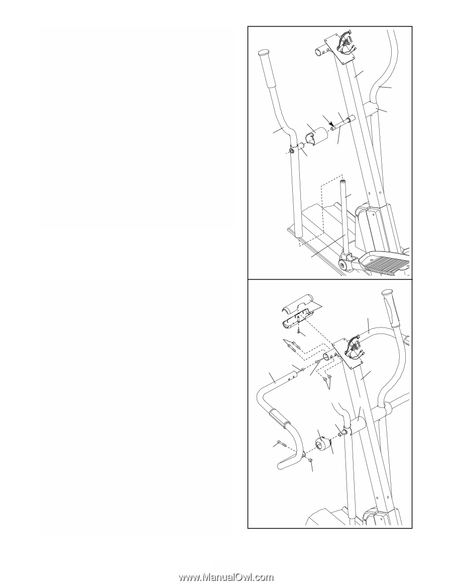
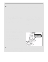
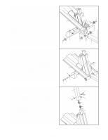
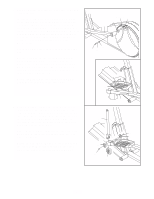
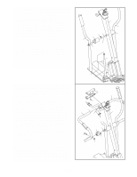
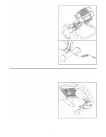
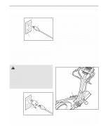
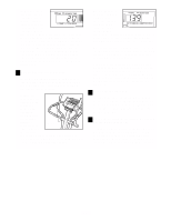
7. Apply a small amount of the included Teflon® lubricant to a paper towel. Rub a thin film of the lubricant onto each Upper Body Leg (31). Identify the Left Upper Body Arm (112), which is marked with an "L" sticker. Slide the Left Upper Body Arm onto the left Upper Body Leg (31). Slide the Right Upper Body Arm (118) onto the right Upper Body Leg (not shown). Make sure that the Upper Body Arms are on the correct sides. Next, slide an Axle Cover (26) onto the post on each Upper Body Arm. Apply grease to the Arm Axle (19). Insert the Arm Axle into the Upright (2), the right Axle Cover (26), and the Right Upper Body Arm (118). Next, push the Arm Axle into the Upright until the left end of the Arm Axle is flush with the left side of the Upright. Then, raise the Left Upper Body Arm (112), and insert the Arm Axle into the left Axle Cover (26) and the Left Upper Body Arm. Center the Arm Axle and rotate it so the indicated hole is in the position shown. 7 112 Hole 19 26 2 118 26 Grease Post 31 8. Have another person hold the Left Handlebar (24) near the Upright (2) as shown. Connect the left Pulse Sensor Wire (20) to the Pulse Extension Wire (101). Slide an Axle Cover Endcap (91) onto the lower end of the Left Handlebar. Slide the upper end of the Left Handlebar (24) into the tube on the front of the Upright (2), while sliding the lower end of the Left Handlebar onto the Arm Axle (19). Attach the upper end of the Left Handlebar with two M8 x 42mm Button Bolts (85) and two M8 Nylon Jam Nuts (86); be careful not to damage the Wires (20, 101) as you insert the Button Bolts. Make sure that the Jam Nuts are resting in the hexagonal holes in the tube on the front of the Upright. Attach the lower end of the Left Handlebar with an M8 x 35mm Button Bolt (105) and an M8 Jam Nut (86). Press the tabs on the Axle Cover Endcap (91) into the left Axle Cover (26). Attach the Right Handlebar (23) to the Upright (2) in the same way. Hold the halves of the Handlebar Cover (25) around the tube on the front of the Upright (2); be careful not to damage the Wires (20, 101). Attach the Handlebar Cover with an M4 x 16mm Round Head Screw (96). Lubricate 8 25 85 96 20 24 101 86 19 91 23 2 26 105 Tab 86 8
-
 1
1 -
2
-
 3
3 -
 4
4 -
 5
5 -
 6
6 -
 7
7 -
 8
8 -
 9
9 -
 10
10 -
 11
11 -
 12
12 -
 13
13 -
14
-
15
-
16
-
17
-
18
-
19
-
20
-
21
-
22
-
23
-
24
-
25
-
26
-
27
-
28
 |
 |