HealthRider Aire Strider E60 Elliptical English Manual - Page 9
Installing The Receiver For The Optional Chest Pulse Sensor
 |
View all HealthRider Aire Strider E60 Elliptical manuals
Add to My Manuals
Save this manual to your list of manuals |
Page 9 highlights
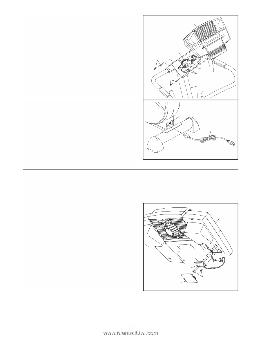
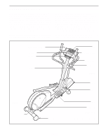
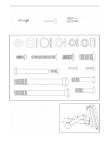
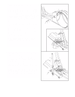
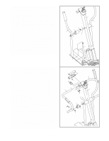
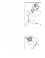
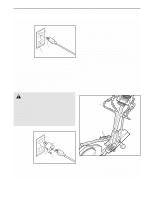
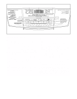
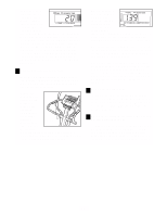
9. Have another person hold the Console (17) near the Upright (2). Connect the Upper Wire Harness (95) to the wire harness on the Console (17). Connect the Pulse Extension Wire (101) to the pulse wire on the Console. Next, locate the two ground wires that are attached to the Upright (2). Connect the ground wires to the two smallest wires on the Console. Carefully insert all excess wiring up into the Console (17) and down into the Upright (2). Attach the Console to the Upright with four M4 x 16mm Screws (98). (Note: The Screws may be found in the console box.) Be careful to avoid pinching the wires. 10. Plug the Power Cord (93) into the Power Socket (92) at the rear of the elliptical exerciser. 11. Make sure that all parts of the elliptical exerciser are properly tightened. Cover the floor beneath the elliptical exerciser to protect the floor from damage. Note: Some extra hardware may be left over. The elliptical exerciser is now fully assembled. If you have purchased the optional chest pulse sensor (see page 21), see the instructions below. 9 17 Do not pinch the wires during this step. 101 98 95 Ground 98 Wires 2 10 92 93 INSTALLING THE RECEIVER FOR THE OPTIONAL CHEST PULSE SENSOR If you have purchased the optional chest pulse sensor (see page 21), follow the steps below to install the receiver included with the optional chest pulse sensor. 1. Look under the Console (17) and locate the access cover. Remove the access cover. 17 2. Hold the receiver in the position shown, with the small cylinder at the top. Using the two screws included with the chest pulse sensor, attach the receiver to the two plastic posts (not shown) inside the access opening in the back of the Console (17). 3. Connect the wire on the receiver to the indicated wire on the Console (17). Make sure that the connectors on the wires snap together. Discard the other wires included with the chest pulse sensor. 4. Reattach the access cover to the Console (17). Cylinder Receiver Access Cover Screws 9
-
 1
1 -
2
-
3
-
 4
4 -
 5
5 -
 6
6 -
 7
7 -
 8
8 -
 9
9 -
 10
10 -
 11
11 -
 12
12 -
 13
13 -
 14
14 -
15
-
16
-
17
-
18
-
19
-
20
-
21
-
22
-
23
-
24
-
25
-
26
-
27
-
28
 |
 |