HP 540 HP 540 Notebook PC HP 541 Notebook PC - Display Replacement Guide - Page 12
Remove the WLAN module, that secure the WLAN module to the computer.
 |
View all HP 540 manuals
Add to My Manuals
Save this manual to your list of manuals |
Page 12 highlights
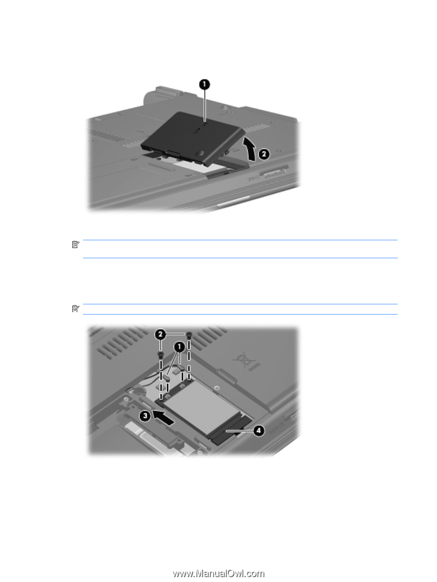
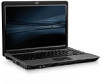
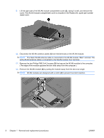
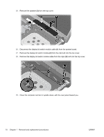
9. Lift the right side of the WLAN module compartment cover (2), swing it to left, and remove the cover. The WLAN module compartment cover is included in the Plastics Kit, spare part number 456614-001. 10. Disconnect the WLAN antenna cables (1) from the terminals on the WLAN module. NOTE: The black WLAN antenna cable is connected to the WLAN module "Main" terminal. The white WLAN antenna cable is connected to the WLAN module "Aux" terminal. 11. Remove the two Phillips PM2.5×4.0 screws (2) that secure the WLAN module to the computer. (The edge of the module opposite the slot rises away from the computer.) 12. Remove the WLAN module (3) by pulling the module away from the slot at an angle. NOTE: WLAN modules are designed with a notch (4) to prevent incorrect insertion. 6 Chapter 1 Removal and replacement procedures ENWW
-
 1
1 -
2
-
3
-
4
-
5
-
6
-
 7
7 -
 8
8 -
 9
9 -
 10
10 -
 11
11 -
 12
12 -
 13
13 -
 14
14 -
 15
15 -
 16
16 -
 17
17 -
18
-
19
-
20
-
21
-
22
-
23
-
24
-
25
-
26
-
27
-
28
-
29
-
30
 |
 |