HP 540 HP 540 Notebook PC HP 541 Notebook PC - Display Replacement Guide - Page 15
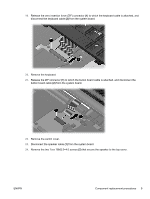
Remove the two Torx T8M2.5×4.0 screws, Disconnect the speaker cable
 |
View all HP 540 manuals
Add to My Manuals
Save this manual to your list of manuals |
Page 15 highlights
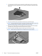
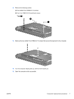
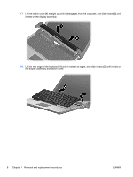
19. Release the zero insertion force (ZIF) connector (1) to which the keyboard cable is attached, and disconnect the keyboard cable (2) from the system board. 20. Remove the keyboard. 21. Release the ZIF connector (1) to which the button board cable is attached, and disconnect the button board cable (2) from the system board. 22. Remove the switch cover. 23. Disconnect the speaker cable (1) from the system board. 24. Remove the two Torx T8M2.5×4.0 screws (2) that secure the speaker to the top cover. ENWW Component replacement procedures 9
-
 1
1 -
2
-
3
-
4
-
5
-
6
-
7
-
8
-
9
-
 10
10 -
 11
11 -
 12
12 -
 13
13 -
 14
14 -
 15
15 -
 16
16 -
 17
17 -
 18
18 -
 19
19 -
 20
20 -
21
-
22
-
23
-
24
-
25
-
26
-
27
-
28
-
29
-
30
 |
 |
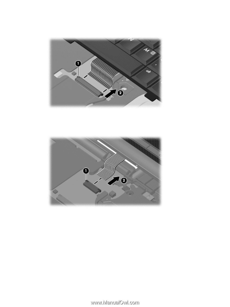
19.
Release the zero insertion force (ZIF) connector
(1)
to which the keyboard cable is attached, and
disconnect the keyboard cable
(2)
from the system board.
20.
Remove the keyboard.
21.
Release the ZIF connector
(1)
to which the button board cable is attached, and disconnect the
button board cable
(2)
from the system board.
22.
Remove the switch cover.
23.
Disconnect the speaker cable
(1)
from the system board.
24.
Remove the two Torx T8M2.5×4.0 screws
(2)
that secure the speaker to the top cover.
ENWW
Component replacement procedures
9