HP 540 HP 540 Notebook PC HP 541 Notebook PC - Display Replacement Guide - Page 13
Two Torx T8M2.5×3.0 broad-head screws, Two slotted Torx ST8M2.5×7.0 screws
 |
View all HP 540 manuals
Add to My Manuals
Save this manual to your list of manuals |
Page 13 highlights
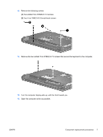
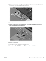
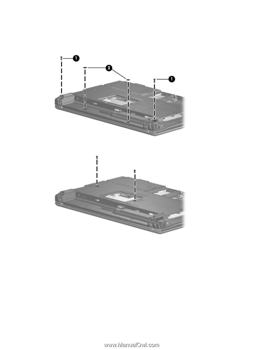
13. Remove the following screws: (1) Two slotted Torx ST8M2.5×7.0 screws (2) Two Torx T8M2.5×3.0 broad-head screws 14. Remove the two slotted Torx ST8M2.5×7.0 screws that secure the keyboard to the computer. 15. Turn the computer display-side up, with the front toward you. 16. Open the computer as far as possible. ENWW Component replacement procedures 7
-
 1
1 -
2
-
3
-
4
-
5
-
6
-
7
-
 8
8 -
 9
9 -
 10
10 -
 11
11 -
 12
12 -
 13
13 -
 14
14 -
 15
15 -
 16
16 -
 17
17 -
 18
18 -
19
-
20
-
21
-
22
-
23
-
24
-
25
-
26
-
27
-
28
-
29
-
30
 |
 |
13.
Remove the following screws:
(1)
Two slotted Torx ST8M2.5×7.0 screws
(2)
Two Torx T8M2.5×3.0 broad-head screws
14.
Remove the two slotted Torx ST8M2.5×7.0 screws that secure the keyboard to the computer.
15.
Turn the computer display-side up, with the front toward you.
16.
Open the computer as far as possible.
ENWW
Component replacement procedures
7