HP 540 HP 540 Notebook PC HP 541 Notebook PC - Display Replacement Guide - Page 18
and the top and bottom sides
 |
View all HP 540 manuals
Add to My Manuals
Save this manual to your list of manuals |
Page 18 highlights
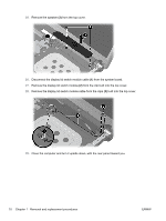
36. Lift the display assembly (2) straight up and remove it. 37. If it is necessary to replace the display bezel, display inverter, or display hinges, remove the eight rubber screw covers (1) and the eight Torx T8M2.5×6.0 screws (2) that secure the display bezel to the display assembly. The rubber screw covers are available in the Rubber Kit, spare part number 500132-001. 38. Flex the inside edges of the left and right sides (1) and the top and bottom sides (2) of the display bezel until the bezel disengages from the display enclosure. 12 Chapter 1 Removal and replacement procedures ENWW
-
 1
1 -
2
-
3
-
4
-
5
-
6
-
7
-
8
-
9
-
10
-
11
-
12
-
 13
13 -
 14
14 -
 15
15 -
 16
16 -
 17
17 -
 18
18 -
 19
19 -
 20
20 -
 21
21 -
 22
22 -
 23
23 -
24
-
25
-
26
-
27
-
28
-
29
-
30
 |
 |
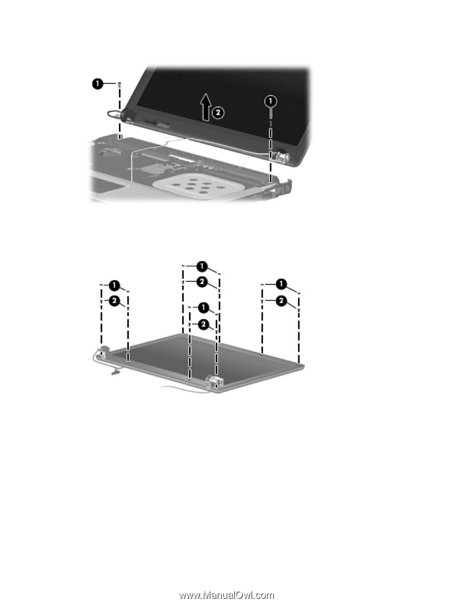
36.
Lift the display assembly
(2)
straight up and remove it.
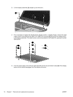
37.
If it is necessary to replace the display bezel, display inverter, or display hinges, remove the eight
rubber screw covers
(1)
and the eight Torx T8M2.5×6.0 screws
(2)
that secure the display bezel
to the display assembly. The rubber screw covers are available in the Rubber Kit, spare part number
500132-001.
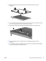
38.
Flex the inside edges of the left and right sides
(1)
and the top and bottom sides
(2)
of the display
bezel until the bezel disengages from the display enclosure.
12
Chapter 1
Removal and replacement procedures
ENWW