HP Color LaserJet CM1312 Service Manual - Page 169
Speaker (fax/memory-card models only), CAUTION
 |
View all HP Color LaserJet CM1312 manuals
Add to My Manuals
Save this manual to your list of manuals |
Page 169 highlights
Speaker (fax/memory-card models only) 1. Remove the following components: ● Right cover. See Right cover on page 132. ● Scanner assembly. See Scanner assembly on page 147. 2. Disconnect one wire-harness connector (callout 1; P2), and then remove one clip (callout 2). Figure 6-73 Remove the speaker (1 of 2) 2 1 3. Remove the speaker from the product. CAUTION: Do not handle the speaker by grasping the wire harness. The solder connections can be easily broken. When handling the speaker, do not push on the speaker cone to prevent damaging it. Figure 6-74 Remove the speaker (2 of 2) ENWW Internal assemblies 155
-
 1
1 -
2
-
3
-
4
-
5
-
6
-
7
-
8
-
9
-
10
-
11
-
12
-
13
-
14
-
15
-
16
-
17
-
18
-
19
-
20
-
21
-
22
-
23
-
24
-
25
-
26
-
27
-
28
-
29
-
30
-
31
-
32
-
33
-
34
-
35
-
36
-
37
-
38
-
39
-
40
-
41
-
42
-
43
-
44
-
45
-
46
-
47
-
48
-
49
-
50
-
51
-
52
-
53
-
54
-
55
-
56
-
57
-
58
-
59
-
60
-
61
-
62
-
63
-
64
-
65
-
66
-
67
-
68
-
69
-
70
-
71
-
72
-
73
-
74
-
75
-
76
-
77
-
78
-
79
-
80
-
81
-
82
-
83
-
84
-
85
-
86
-
87
-
88
-
89
-
90
-
91
-
92
-
93
-
94
-
95
-
96
-
97
-
98
-
99
-
100
-
101
-
102
-
103
-
104
-
105
-
106
-
107
-
108
-
109
-
110
-
111
-
112
-
113
-
114
-
115
-
116
-
117
-
118
-
119
-
120
-
121
-
122
-
123
-
124
-
125
-
126
-
127
-
128
-
129
-
130
-
131
-
132
-
133
-
134
-
135
-
136
-
137
-
138
-
139
-
140
-
141
-
142
-
143
-
144
-
145
-
146
-
147
-
148
-
149
-
150
-
151
-
152
-
153
-
154
-
155
-
156
-
157
-
158
-
159
-
160
-
161
-
162
-
163
-
 164
164 -
 165
165 -
 166
166 -
 167
167 -
 168
168 -
 169
169 -
 170
170 -
 171
171 -
 172
172 -
 173
173 -
 174
174 -
175
-
176
-
177
-
178
-
179
-
180
-
181
-
182
-
183
-
184
-
185
-
186
-
187
-
188
-
189
-
190
-
191
-
192
-
193
-
194
-
195
-
196
-
197
-
198
-
199
-
200
-
201
-
202
-
203
-
204
-
205
-
206
-
207
-
208
-
209
-
210
-
211
-
212
-
213
-
214
-
215
-
216
-
217
-
218
-
219
-
220
-
221
-
222
-
223
-
224
-
225
-
226
-
227
-
228
-
229
-
230
-
231
-
232
-
233
-
234
-
235
-
236
-
237
-
238
-
239
-
240
-
241
-
242
-
243
-
244
-
245
-
246
-
247
-
248
-
249
-
250
-
251
-
252
-
253
-
254
-
255
-
256
-
257
-
258
-
259
-
260
-
261
-
262
-
263
-
264
-
265
-
266
-
267
-
268
-
269
-
270
-
271
-
272
-
273
-
274
-
275
-
276
-
277
-
278
-
279
-
280
-
281
-
282
-
283
-
284
-
285
-
286
-
287
-
288
-
289
-
290
-
291
-
292
-
293
-
294
-
295
-
296
-
297
-
298
-
299
-
300
-
301
-
302
-
303
-
304
-
305
-
306
-
307
-
308
-
309
-
310
-
311
-
312
-
313
-
314
-
315
-
316
-
317
-
318
-
319
-
320
-
321
-
322
-
323
-
324
-
325
-
326
-
327
-
328
-
329
-
330
-
331
-
332
-
333
-
334
 |
 |

Speaker (fax/memory-card models only)
1.
Remove the following components:
●
Right cover. See
Right cover
on page
132
.
●
Scanner assembly. See
Scanner assembly
on page
147
.
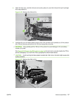
2.
Disconnect one wire-harness connector (callout 1; P2), and then remove one clip (callout 2).
Figure 6-73
Remove the speaker (1 of 2)
1
2
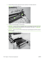
3.
Remove the speaker from the product.
CAUTION:
Do not handle the speaker by grasping the wire harness. The solder connections can
be easily broken.
When handling the speaker, do not push on the speaker cone to prevent damaging it.
Figure 6-74
Remove the speaker (2 of 2)
ENWW
Internal assemblies
155