HP Dv4-1124nr HP Pavilion dv4 Entertainment PC - Display Replacement Guide - Page 16
Help and Support - keyboard
 |
UPC - 884420609841
View all HP Dv4-1124nr manuals
Add to My Manuals
Save this manual to your list of manuals |
Page 16 highlights
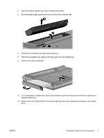
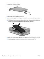
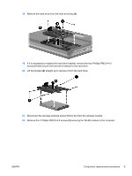
23. Remove the WLAN module (3) by pulling it away from the slot at an angle. (The edge of the module opposite the slot rises away from the computer.) NOTE: WLAN modules are designed with a notch (4) to prevent incorrect insertion into the WLAN module slot. CAUTION: The WWAN module and the WLAN module are not interchangeable. CAUTION: To prevent an unresponsive system, replace the wireless module only with a wireless module authorized for use in the computer by the governmental agency that regulates wireless devices in your country or region. If you replace the module and then receive a warning message, remove the module to restore computer functionality, and then contact technical support through Help and Support. 24. Turn the computer upside down, with the front toward you. 25. Remove the two Phillips PM2.5×17.0 screws (1), and the Phillips PM2.5×9.0 screw (2) that secure the keyboard to the computer. 26. Turn the computer display-side up, with the front toward you. 10 Chapter 1 Removal and replacement procedures ENWW
-
 1
1 -
2
-
3
-
4
-
5
-
6
-
7
-
8
-
9
-
10
-
 11
11 -
 12
12 -
 13
13 -
 14
14 -
 15
15 -
 16
16 -
 17
17 -
 18
18 -
 19
19 -
 20
20 -
 21
21 -
22
-
23
-
24
-
25
-
26
-
27
-
28
-
29
-
30
-
31
-
32
-
33
-
34
-
35
-
36
-
37
-
38
 |
 |
