HP Dv4-1124nr HP Pavilion dv4 Entertainment PC - Display Replacement Guide - Page 25
Remove the tape, Release the foil shield covering the display panel cable
 |
UPC - 884420609841
View all HP Dv4-1124nr manuals
Add to My Manuals
Save this manual to your list of manuals |
Page 25 highlights
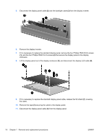
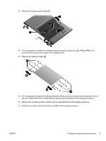
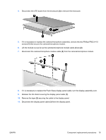
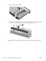
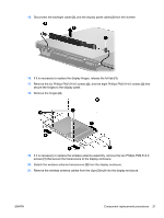
4. Disconnect the LED board from the enclosure (3) to remove the enclosure. 5. If it is necessary to replace the camera/microphone assembly, remove the two Phillips PM2.5×4.0 screws (1) that secure the camera/microphone module. 6. Lift the module out as far as the camera/microphone module cable allows (2). 7. Disconnect the camera/microphone module cable (3) from the camera/microphone module. 8. If it is necessary to replace the Flush Glass display panel cable, turn the display assembly over. 9. Release the foil shield covering the display panel cable (1). 10. Remove the tape (2) securing the cable to the display panel. 11. Disconnect the display panel cable (3) from the display panel. ENWW Component replacement procedures 19
-
 1
1 -
2
-
3
-
4
-
5
-
6
-
7
-
8
-
9
-
10
-
11
-
12
-
13
-
14
-
15
-
16
-
17
-
18
-
19
-
 20
20 -
 21
21 -
 22
22 -
 23
23 -
 24
24 -
 25
25 -
 26
26 -
 27
27 -
 28
28 -
 29
29 -
 30
30 -
31
-
32
-
33
-
34
-
35
-
36
-
37
-
38
 |
 |
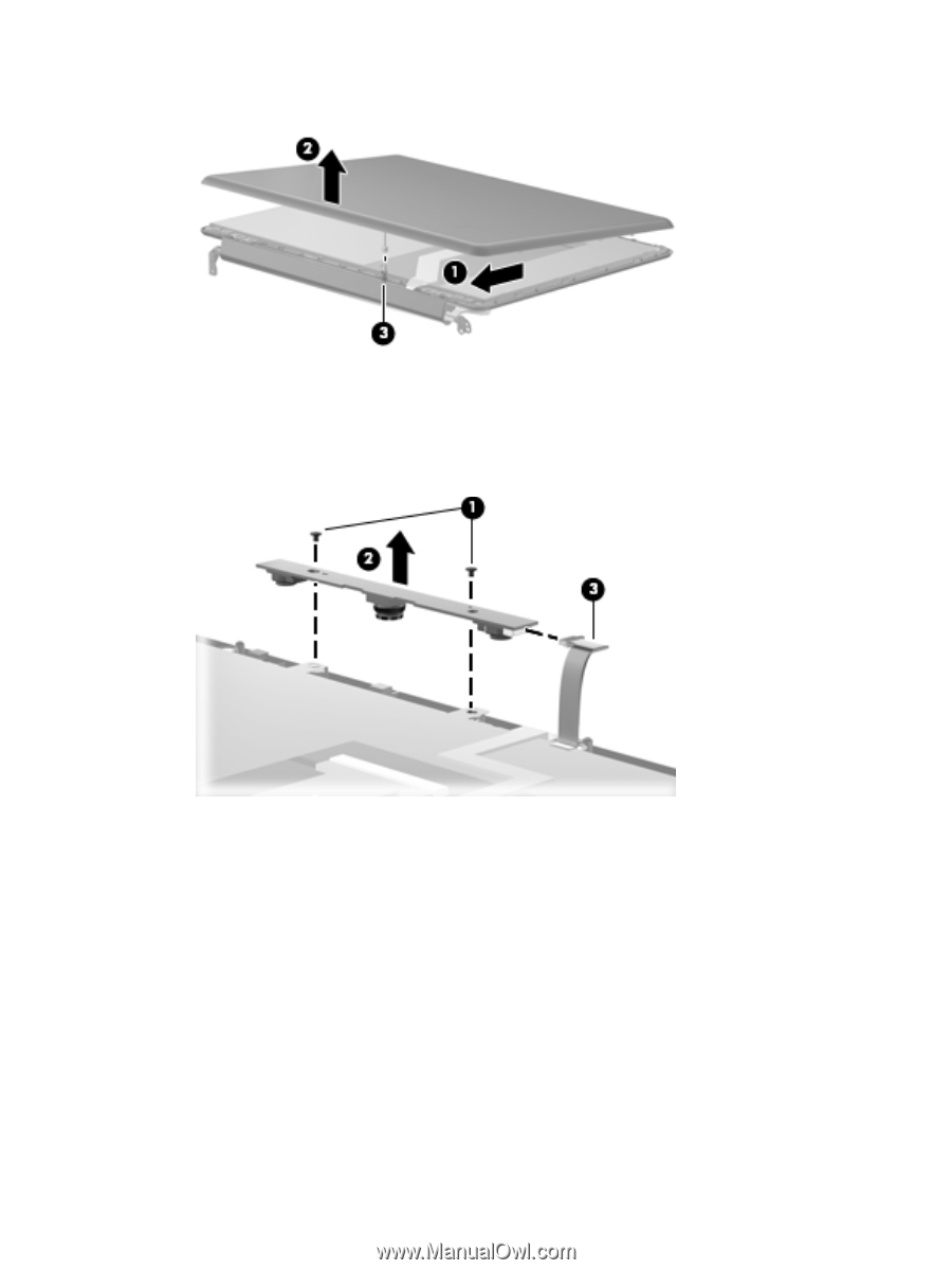
4.
Disconnect the LED board from the enclosure
(3)
to remove the enclosure.
5.
If it is necessary to replace the camera/microphone assembly, remove the two Phillips PM2.5×4.0
screws
(1)
that secure the camera/microphone module.
6.
Lift the module out as far as the camera/microphone module cable allows
(2)
.
7.
Disconnect the camera/microphone module cable
(3)
from the camera/microphone module.
8.
If it is necessary to replace the Flush Glass display panel cable, turn the display assembly over.
9.
Release the foil shield covering the display panel cable
(1)
.
10.
Remove the tape
(2)
securing the cable to the display panel.
11.
Disconnect the display panel cable
(3)
from the display panel.
ENWW
Component replacement procedures
19