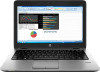
HP EliteBook 720 Maintenance and Service Guide
HP EliteBook 720 Manual
 |
View all HP EliteBook 720 manuals
Add to My Manuals
Save this manual to your list of manuals |
HP EliteBook 720 manual content summary:
- HP EliteBook 720 | Maintenance and Service Guide - Page 1
HP EliteBook 820 G2 Notebook PC and HP EliteBook 720 G2 Notebook PC Maintenance and Service Guide - HP EliteBook 720 | Maintenance and Service Guide - Page 2
and services. Nothing herein should be construed as constituting an additional warranty. HP shall not be liable for technical or editorial errors or omissions contained herein. Second Edition: August 2015 First Edition: January 2015 Document Part Number: 791152-002 Product notice This user guide - HP EliteBook 720 | Maintenance and Service Guide - Page 3
Safety warning notice WARNING! To reduce the possibility of heat-related injuries or of overheating the device, do not place the device directly on your lap or obstruct the device air vents. Use the device only on a hard, flat surface. Do not allow another hard surface, such as an adjoining optional - HP EliteBook 720 | Maintenance and Service Guide - Page 4
iv Safety warning notice - HP EliteBook 720 | Maintenance and Service Guide - Page 5
Wireless networking ...4 External expansion ...4 Ports ...5 Docking ...5 Keyboard/pointing devices ...5 Power requirements ...5 Security ...6 Operating system ...6 Serviceability ...8 2 External component identification ...9 Display ...9 Front ...10 Right ...11 Left ...12 Top ...13 TouchPad ...13 - HP EliteBook 720 | Maintenance and Service Guide - Page 6
for Customer Self-Repair parts 37 Component replacement procedures ...37 Service cover ...37 Battery ...39 Hard drive/solid-state drive ...41 procedures ...55 Unlocking the device and disabling Always On Remote Management (select HP devices only) ..... 55 RTC battery ...56 Top cover ...57 Display - HP EliteBook 720 | Maintenance and Service Guide - Page 7
91 Dynamically choosing a boot device using the f9 prompt 92 Setting a MultiBoot Express prompt 92 Entering MultiBoot Express preferences 92 9 Computer Setup (BIOS), TPM, and HP Sure Start in Windows 10 93 Using Computer Setup ...93 Starting Computer Setup ...93 vii - HP EliteBook 720 | Maintenance and Service Guide - Page 8
USB device 98 11 Backup and recovery in Windows 7 ...99 Creating recovery media and backups ...99 Guidelines ...99 Creating recovery media with HP Recovery Disc Creator 99 Creating recovery media 100 Backing up your information ...100 Performing a system recovery ...101 Using the Windows recovery - HP EliteBook 720 | Maintenance and Service Guide - Page 9
products only 111 14 Specifications ...112 15 Statement of memory volatility ...113 Nonvolatile memory usage ...115 Questions and answers ...117 Using HP Sure Start (select models only) ...118 16 Power cord set requirements ...119 Requirements for all countries ...119 Requirements for specific - HP EliteBook 720 | Maintenance and Service Guide - Page 10
x - HP EliteBook 720 | Maintenance and Service Guide - Page 11
1 Product description Product Name Description HP EliteBook 720 G2 Notebook PC HP EliteBook 820 G2 Notebook PC 720 G2 models × 820 G2 models × Chipset Description Intel® processor controller hub (PCH), soldered on circuit (SoC) 720 G2 models × 820 G2 models × Processor Description 5th - HP EliteBook 720 | Maintenance and Service Guide - Page 12
2) ● 2048-MB total system memory (2048 MB × 1) Flash cache Description Support for 32-GB solid-state drive (M.2 form factor) Intel SRT (Smart Response description 720 G2 models × 820 G2 models × 720 G2 models × 820 G2 models × 720 G2 models × 820 G2 models × 720 G2 models × 820 G2 models - HP EliteBook 720 | Maintenance and Service Guide - Page 13
, SATA-3, SED, Opal 2, solid-state drive Audio and video Description Webcam, 720p Supports "No camera" option Dual array microphones Stereo speakers (2) Realtek ALC3228 HD audio with DTS Studio sound 720 G2 models × × 820 G2 models × × × × × 720 G2 models × 820 G2 models × Primary storage 3 - HP EliteBook 720 | Maintenance and Service Guide - Page 14
● HP lt4111 LTE/EV-DO/HSPA+ Mobile Broadband Module Integrated NFC module NFC antenna Supports "No NFC" option External expansion Description SD media reader slot Support for SD, SDHC, SDXC Push-push insertion/removal SIM slot (populated with WWAN; tool-less user-accessible) 720 G2 models × 820 G2 - HP EliteBook 720 | Maintenance and Service Guide - Page 15
VGA (Dsub 15 pin) supporting: 1920×1200 external resolution @ 75 Hz, hot plug and unplug and autodetection for correct output to wide-aspect vs. standard aspect video 720 G2 820 G2 models models × × Docking Description HP UltraSlim Docking Station HP Docking Station 720 G2 820 G2 models models - HP EliteBook 720 | Maintenance and Service Guide - Page 16
Description ● 45-W HP Smart adapter Support for the following power cords: ● 3-wire plug, 1.0 m ● 3-wire plug, 1.8 m ● 2-wire plug, 1.0 m 720 G2 820 G2 models models × × Security Description Support for the following: ● Fingerprint reader ● ● Support for "No fingerprint reader" option ● Security - HP EliteBook 720 | Maintenance and Service Guide - Page 17
or less is selected) ● Windows 7 Professional 64-bit, Service Pack 1 ● Windows 7 Professional 64-bit, Service Pack 1-MSNA ● Ubuntu Linux (not available with WWAN or touch -only support: ● Windows 10 Enterprise ● Windows 8.1 Enterprise 64 ● Windows 8.1 Professional 64 720 G2 models 820 G2 models - HP EliteBook 720 | Maintenance and Service Guide - Page 18
7 Enterprise 32 Serviceability Description End user replaceable parts: ● AC adapter ● Battery (system) ● Hard drive ● Keyboard ● Memory module ● Solid-state drive ● WLAN module ● WWAN module ● M.2 (NGFF) Flash cache / SSD 720 G2 models 820 G2 models 720 G2 models × 820 G2 models × 8 Chapter - HP EliteBook 720 | Maintenance and Service Guide - Page 19
use the webcam: Windows 7: Select Start > All Programs > Communication and Chat > CyberLink YouCam. Windows 8.1: Access HP Support Assistant. To access HP Support Assistant, from the Start screen, select the HP Support Assistant app. Windows 10: Type camera in the taskbar search box, and then select - HP EliteBook 720 | Maintenance and Service Guide - Page 20
Safety, and Environmental Notices that applies to your country or region. To access this guide: Windows 7: Select Start > Help and Support > User Guides. Windows 8.1: From the Start screen, type support, and then select the HP Support Assistant app. Windows 10: Select Start, select All apps, select - HP EliteBook 720 | Maintenance and Service Guide - Page 21
, Safety, and Environmental Notices. To access this document: Windows 7: Select Start > Help and Support > User Guides. Windows 8.1: From the Start screen, type support, and then select the HP Support Assistant app. ‒ or - From the Windows desktop, click the question mark icon in the - HP EliteBook 720 | Maintenance and Service Guide - Page 22
Component (4) (5) (6) (7) Memory card reader RJ-45 (network) jack/lights Docking connector Power connector Description Reads optional memory cards that store, manage, share, or access information. Connects a network cable. ● Green (left): The network is connected. ● Amber (right): Activity is - HP EliteBook 720 | Maintenance and Service Guide - Page 23
. Turns the TouchPad on and off. Reads your finger gestures to move the pointer or activate items on the screen. NOTE: The TouchPad also supports edge-swipe gestures. Functions like the left button on an external mouse. Functions like the right button on an external mouse. Functions like the right - HP EliteBook 720 | Maintenance and Service Guide - Page 24
Lights NOTE: Your computer may look slightly different from the illustration in this section. Component (1) Power light (2) Caps lock light (3) TouchPad light (4) Microphone mute light (5) Num lock light (6) Wireless light (7) Mute light 14 Chapter 2 External component identification - HP EliteBook 720 | Maintenance and Service Guide - Page 25
Buttons, speakers, and fingerprint reader (select models only) Component (1) Power button (2) Speakers Description ● When the computer is off, press the button to turn on the computer. ● When the computer is on, press the button briefly to initiate Sleep. ● When the computer is in the Sleep - HP EliteBook 720 | Maintenance and Service Guide - Page 26
Component (3) Wireless button Description Turns the wireless feature on or off but does not establish a wireless connection. (4) Volume mute button Mutes and restores speaker sound. (5) Fingerprint reader (select Allows a fingerprint logon to Windows, instead of a password logon. models - HP EliteBook 720 | Maintenance and Service Guide - Page 27
Component (6) (7) Windows applications key num lk key Description Windows 7: Displays a shortcut menu for items beneath the cursor. Windows 8.1: Displays options for a selected object. Windows 10: Displays options for a selected object. Turns the embedded numeric keypad on and off when pressed in - HP EliteBook 720 | Maintenance and Service Guide - Page 28
battery. only) Service door Provides access to support through HP Support Assistant. To access Help and Support in Windows 7, select Start > Help and Support. To access HP Support Assistant in Windows 8.1, from the Start screen, select the HP Support Assistant app. Windows 10: Type support - HP EliteBook 720 | Maintenance and Service Guide - Page 29
door. Locks the service door. Enable airflow to cool internal components. NOTE: The computer fan starts up automatically to cool internal components and prevent overheating. It is normal for the internal fan to cycle on and off during routine operation. Supports a wireless subscriber identity - HP EliteBook 720 | Maintenance and Service Guide - Page 30
3 Illustrated parts catalog NOTE: HP continually improves and changes product parts. For complete and current information on supported parts for your computer, go to http://partsurfer.hp.com, select your country or region, and then follow the on-screen instructions. Computer major components 20 - HP EliteBook 720 | Maintenance and Service Guide - Page 31
Item Component Spare part number (1) Display assembly: The TouchScreen display assembly is spared as a whole unit replacement. 12.5-in, AntiGlare, FHD, LED, UWVA, TouchScreen display assembly 781838-001 The non-TouchScreen display assembly is spared at the subcomponent level only. For more - HP EliteBook 720 | Maintenance and Service Guide - Page 32
Item Component For use in Taiwan For use in Thailand For use in Turkey For use in the United Kingdom For use in the United States Keyboard without backlight (includes keyboard cable): For use in models without a backlit keyboard: For use in Belgium For use in Brazil For use in Bulgaria For use in - HP EliteBook 720 | Maintenance and Service Guide - Page 33
Core i5-5200U processor 781855-xxx Intel Core i3-5010U processor 781854-xxx (14) Base enclosure (includes RJ-45 cover, rubber feet, and service cover eject latch assembly): 765603-001 Rubber Kit (not illustrated, includes base enclosure rubber screw covers) 730550-001 (15) Hard drive (does - HP EliteBook 720 | Maintenance and Service Guide - Page 34
Memory module (PCL3, 12800, 1600-MHz): 8 GB 693374-001 4 GB 691740-001 WWAN module: HP hs3110 HSPA+ Mobile Broadband Module 822828-001 HP lt4112 LTE/HPSA+ Mobile Broadband Module 790198-001 HP lt4211 LTE/EV-DO/HSPA+ Mobile Broadband Module 793116-001 Solid-state drive: NOTE: M.2 drive - HP EliteBook 720 | Maintenance and Service Guide - Page 35
Item Component (21) Service cover (includes rubber feet): For use in 820 G2 models For use in 720 G2 models For use only on RCTO models Plastics Kit Spare part number 781836-001 790080-001 797517-001 Item Component Plastics Kit, includes: (1) Card reader - HP EliteBook 720 | Maintenance and Service Guide - Page 36
display assembly. Item (1) (2) Component Display bezel: For use on 720 G2 models with an HD display panel For use on 720 G2 models with an FHD display panel For use on 820 G2 models with an HD display panel For use on 820 G2 models with an FHD display panel Webcam/microphone module (includes - HP EliteBook 720 | Maintenance and Service Guide - Page 37
models equipped with an FHD display 775893-001 For use only on computer models equipped with an HD display 730561-001 Display Panel Support Kit (not illustrated, includes display enclosure, WLAN antenna cables and transceivers, and WWAN antenna cables and transceivers): For use only on computer - HP EliteBook 720 | Maintenance and Service Guide - Page 38
Mass storage devices Item (1) Component Spare part number Hard drive (does not include hard drive bracket, hard drive connector adapter, or screws): NOTE: The hard drive bracket, hard drive connector adapter, and screws are included in the Hard Drive Hardware Kit, spare part number 730539-001. - HP EliteBook 720 | Maintenance and Service Guide - Page 39
connector) Smart AC adapter dongle, 7.4mm HP DisplayPort-to-HDMI 1.4 adapter Carrying case: HP Essential top-load carrying case HP business top-load carrying case HP 2013 UltraSlim Docking Station HP Mobile Connect SIM module Lock: HP docking station cable lock HP ultraslim keyed cable lock Mouse - HP EliteBook 720 | Maintenance and Service Guide - Page 40
Component HP USB laser mouse HP USB travel mouse Power cord (3-pin, black, 1.83-m): For use in Argentina For use in Australia For use in Brazil For use in Denmark For - HP EliteBook 720 | Maintenance and Service Guide - Page 41
Component For use in Switzerland For use in Taiwan For use in Thailand For use in the United Kingdom and Singapore Power cord for use in Japan (2-pin, black, 1.00-m): Screw Kit Mylar tape Pointing stick covers, black (20 pieces) Spare part number 755530-111 755530-AB1 755530-201 755530-031 762689- - HP EliteBook 720 | Maintenance and Service Guide - Page 42
Flat-bladed screw driver ● Magnetic screw driver ● Phillips P0 screw driver Service considerations The following sections include some of the considerations that you must keep only at the points designated in the maintenance instructions. 32 Chapter 4 Removal and replacement preliminary requirements - HP EliteBook 720 | Maintenance and Service Guide - Page 43
Cables and connectors CAUTION: When servicing the computer, be sure that cables are placed in their proper locations during the reassembly process. Improper cable placement can damage the computer. Cables must - HP EliteBook 720 | Maintenance and Service Guide - Page 44
CAUTION: To prevent damage to the computer when you are removing or installing internal components, observe these precautions: Keep components in their electrostatic-safe containers until you are ready to install them. Before touching an electronic component, discharge static electricity by using - HP EliteBook 720 | Maintenance and Service Guide - Page 45
material. ● Use a wrist strap connected to a properly grounded work surface and use properly grounded tools and equipment. ● Use conductive field service tools, such as cutters, screw drivers, and vacuums. ● When fixtures must directly contact dissipative surfaces, use fixtures made only of static - HP EliteBook 720 | Maintenance and Service Guide - Page 46
with ground cords of one megohm resistance ● Static-dissipative tables or floor mats with hard ties to the ground ● Field service kits ● Static awareness labels ● Material-handling packages ● Nonconductive plastic bags, tubes, or boxes ● Metal tote boxes ● Electrostatic voltage levels and - HP EliteBook 720 | Maintenance and Service Guide - Page 47
of each screw size and location during removal and replacement. Service cover NOTE: The service cover spare part kit includes rubber feet. Description Service cover for use in 820 G2 models Service cover for use in 720 G2 models Service cover for use only on RCTO models Spare part number 781836 - HP EliteBook 720 | Maintenance and Service Guide - Page 48
6. Remove the service cover (5). Reverse this procedure to install the service cover. 38 Chapter 5 Removal and replacement procedures for Customer Self-Repair parts - HP EliteBook 720 | Maintenance and Service Guide - Page 49
cover (see Service cover on page 37). WARNING! To reduce potential safety issues, use only the battery provided with the computer, a replacement battery provided by HP, or a compatible battery purchased from HP. CAUTION: Removing a battery that is the sole power source for the computer can cause - HP EliteBook 720 | Maintenance and Service Guide - Page 50
2. Use the release tab (2) to lift the rear edge of the battery (3) until the battery rests at an angle. 3. Remove the battery. Reverse this procedure to install the battery. 40 Chapter 5 Removal and replacement procedures for Customer Self-Repair parts - HP EliteBook 720 | Maintenance and Service Guide - Page 51
the power from the computer by unplugging the power cord from the computer. 3. Disconnect all external devices from the computer. 4. Remove the service cover (see Service cover on page 37). 5. Remove the battery (see Battery on page 39). Remove the hard drive: 1. Loosen the four Phillips captive - HP EliteBook 720 | Maintenance and Service Guide - Page 52
2. Use the release tab (2) to remove the hard drive. 3. If it is necessary to disassemble the hard drive, perform the following steps: a. Position the hard drive with the rear toward you. b. Remove the four Phillips PM2.75×3.5 screws (1) that secure the hard drive bracket to the hard drive. c. - HP EliteBook 720 | Maintenance and Service Guide - Page 53
d. Remove the hard drive connector adapter (3) from the hard drive. The hard drive bracket, hard drive connector adapter, and screws are available in the Hard Drive Hardware Kit, spare part number 730539-001. Reverse this procedure to reassemble and install the hard drive. Component replacement - HP EliteBook 720 | Maintenance and Service Guide - Page 54
WWAN module Description HP hs3110 HSPA+ Mobile Broadband Module HP lt4112 LTE/HPSA+ Mobile Broadband Module HP lt4111 LTE/EV-DO/ the computer. 3. Disconnect all external devices from the computer. 4. Remove the service cover (see Service cover on page 37). 5. Remove the battery (see Battery on page - HP EliteBook 720 | Maintenance and Service Guide - Page 55
Reverse this procedure to install the WWAN module. Component replacement procedures 45 - HP EliteBook 720 | Maintenance and Service Guide - Page 56
the power from the computer by unplugging the power cord from the computer. 3. Disconnect all external devices from the computer. 4. Remove the service cover (see Service cover on page 37). 5. Remove the battery (see Battery on page 39). Remove the solid-state drive: 1. Remove the Phillips PM2 - HP EliteBook 720 | Maintenance and Service Guide - Page 57
the power from the computer by unplugging the power cord from the computer. 3. Disconnect all external devices from the computer. 4. Remove the service cover (see Service cover on page 37). 5. Remove the battery (see Battery on page 39). Remove the WLAN module: 1. Disconnect the WLAN antenna cables - HP EliteBook 720 | Maintenance and Service Guide - Page 58
Reverse this procedure to install the WLAN module. 48 Chapter 5 Removal and replacement procedures for Customer Self-Repair parts - HP EliteBook 720 | Maintenance and Service Guide - Page 59
the power from the computer by unplugging the power cord from the computer. 3. Disconnect all external devices from the computer. 4. Remove the service cover (see Service cover on page 37). 5. Remove the battery (see Battery on page 39). Remove the memory module: 1. Spread the retaining tabs (1) on - HP EliteBook 720 | Maintenance and Service Guide - Page 60
Keyboard For use in country or region Spare part number For use in country or region Spare part number Keyboard with backlight (includes backlight cable and keyboard cable): For use in Belgium 776452-A41 For use in Northwest Africa 776452-FP1 For use in Brazil 776452-201 For use in Norway - HP EliteBook 720 | Maintenance and Service Guide - Page 61
the power from the computer by unplugging the power cord from the computer. 3. Disconnect all external devices from the computer. 4. Remove the service cover (see Service cover on page 37). 5. Remove the battery (see Battery on page 39). Remove the keyboard: 1. Loosen the two captive screws that - HP EliteBook 720 | Maintenance and Service Guide - Page 62
4. Insert a thin, plastic tool into the keyboard release hole next to the fan, and then press on the back of the keyboard until the keyboard disengages from the computer. 5. Open the computer as far as it will open. 6. Lift the rear edge of the keyboard (1) until it rests at an angle. 7. Slide the - HP EliteBook 720 | Maintenance and Service Guide - Page 63
8. Swing the rear edge of the keyboard (3) up and forward until it rests upside down on the palm rest. NOTE: Step 9 applies only to computer models equipped with a keyboard with backlight. 9. Release the zero insertion force (ZIF) connector (1) to which the backlight cable is attached, and then - HP EliteBook 720 | Maintenance and Service Guide - Page 64
12. Remove the keyboard (7). Reverse this procedure to install the keyboard. 54 Chapter 5 Removal and replacement procedures for Customer Self-Repair parts - HP EliteBook 720 | Maintenance and Service Guide - Page 65
current information on supported parts for your computer, go to http://partsurfer.hp.com, select your country or region, and then follow the on-screen instructions. Component replacement procedures This chapter provides removal and replacement procedures for Authorized Service Provider only parts - HP EliteBook 720 | Maintenance and Service Guide - Page 66
the power from the computer by unplugging the power cord from the computer. 3. Disconnect all external devices from the computer. 4. Remove the service cover (see Service cover on page 37). 5. Remove the battery (see Battery on page 39). 6. Remove the keyboard (see Keyboard on page 50). Remove the - HP EliteBook 720 | Maintenance and Service Guide - Page 67
the power from the computer by unplugging the power cord from the computer. 3. Disconnect all external devices from the computer. 4. Remove the service cover (see Service cover on page 37), and then remove the following components: a. Battery (see Battery on page 39) b. Hard drive (see Hard drive - HP EliteBook 720 | Maintenance and Service Guide - Page 68
a "3" marking on the inside of the cover 7. Remove the card reader bezel (4) from the card reader slot. 58 Chapter 6 Removal and replacement procedures for Authorized Service Provider parts - HP EliteBook 720 | Maintenance and Service Guide - Page 69
8. Remove the ten Torx T8M2.5×6.5 screws that secure the top cover to the base enclosure. 9. Remove the following screws that secure the top cover to the base enclosure: (1) One Phillips PM2.0×6.5 screw (2) Three Phillips PM2.5×4.5 screws (3) Two Phillips PM2.0×3.0 screws 10. Remove the two Phillips - HP EliteBook 720 | Maintenance and Service Guide - Page 70
11. Remove the top cover (2). Reverse this procedure to install the top cover. 60 Chapter 6 Removal and replacement procedures for Authorized Service Provider parts - HP EliteBook 720 | Maintenance and Service Guide - Page 71
the power from the computer by unplugging the power cord from the computer. 3. Disconnect all external devices from the computer. 4. Remove the service cover (see Service cover on page 37), and then remove the following components: a. Battery (see Battery on page 39) b. Hard drive (see Hard drive - HP EliteBook 720 | Maintenance and Service Guide - Page 72
G2 models with an HD display panel ● 790381-001: For use on 720 G2 models with an FHD display panel ● 730544-001: For use on 820 G2 models with an HD display panel ● 781837-001: For use on 820 G2 models with an FHD display panel 62 Chapter 6 Removal and replacement procedures for Authorized Service - HP EliteBook 720 | Maintenance and Service Guide - Page 73
6. If it is necessary to replace the display panel: a. Remove the six Phillips PM2.0×3.25 screws (1) that secure the display panel to the display enclosure. CAUTION: Before turning the display panel upside down, make sure the work surface is clear of tools, screws, and any other foreign objects. - HP EliteBook 720 | Maintenance and Service Guide - Page 74
display enclosure with double-sided adhesive.) b. Disconnect the webcam/microphone module cable (2) from the webcam/ microphone module. 64 Chapter 6 Removal and replacement procedures for Authorized Service Provider parts - HP EliteBook 720 | Maintenance and Service Guide - Page 75
c. Remove the webcam/microphone module (3). The webcam/microphone module is available using spare part number 781861-001. The microphone module is available using spare part number 730795-001. 8. If it is necessary to replace the display panel cable: a. Detach the display panel cable (1) from the - HP EliteBook 720 | Maintenance and Service Guide - Page 76
WLAN antenna cables from the clips (2) built into the left and right sides of the display enclosure. 66 Chapter 6 Removal and replacement procedures for Authorized Service Provider parts - HP EliteBook 720 | Maintenance and Service Guide - Page 77
c. Remove the WLAN antenna cables and transceivers (3). The WLAN antenna cables and transceivers are included in the Antenna Kits, spare part numbers 781834-001 (for use only on computer models equipped with an HD display) and 781835-001 (for use only on computer models equipped with an FHD display - HP EliteBook 720 | Maintenance and Service Guide - Page 78
the power from the computer by unplugging the power cord from the computer. 3. Disconnect all external devices from the computer. 4. Remove the service cover (see Service cover on page 37), and then remove the following components: a. Battery (see Battery on page 39) b. Hard drive (see Hard drive - HP EliteBook 720 | Maintenance and Service Guide - Page 79
the power from the computer by unplugging the power cord from the computer. 3. Disconnect all external devices from the computer. 4. Remove the service cover (see Service cover on page 37), and then remove the following components: a. Battery (see Battery on page 39) b. Hard drive (see Hard drive - HP EliteBook 720 | Maintenance and Service Guide - Page 80
the power from the computer by unplugging the power cord from the computer. 3. Disconnect all external devices from the computer. 4. Remove the service cover (see Service cover on page 37), and then remove the following components: a. Battery (see Battery on page 39) b. Hard drive (see Hard drive - HP EliteBook 720 | Maintenance and Service Guide - Page 81
6. Remove the three Philllips PM2.0×2.0 broad head screws (3) that secure the card reader board to the top cover. 7. Remove the card reader board and cable (4). 8. Remove the card reader board and cable. Reverse this procedure to install the card reader board. Component replacement procedures 71 - HP EliteBook 720 | Maintenance and Service Guide - Page 82
the power from the computer by unplugging the power cord from the computer. 3. Disconnect all external devices from the computer. 4. Remove the service cover (see Service cover on page 37), and then remove the following components: a. Battery (see Battery on page 39) b. Hard drive (see Hard drive - HP EliteBook 720 | Maintenance and Service Guide - Page 83
is included with the heat sink and system board spare part kits. Thermal paste is used on the processor (1) and the heat sink section (2) that services it. Reverse this procedure to install the heat sink. Component replacement procedures 73 - HP EliteBook 720 | Maintenance and Service Guide - Page 84
the power from the computer by unplugging the power cord from the computer. 3. Disconnect all external devices from the computer. 4. Remove the service cover (see Service cover on page 37), and then remove the following components: a. Battery (see Battery on page 39) b. Hard drive (see Hard drive - HP EliteBook 720 | Maintenance and Service Guide - Page 85
is included with the heat sink and system board spare part kits. Thermal paste is used on the processor (1) and the heat sink section (2) that services it. Reverse this procedure to install the fan. Component replacement procedures 75 - HP EliteBook 720 | Maintenance and Service Guide - Page 86
the power from the computer by unplugging the power cord from the computer. 3. Disconnect all external devices from the computer. 4. Remove the service cover (see Service cover on page 37), and then remove the following components: a. Battery (see Battery on page 39) b. Hard drive (see Hard drive - HP EliteBook 720 | Maintenance and Service Guide - Page 87
1. Turn the top cover upside down with the front toward you. 2. Release the ZIF connector (1) to which the power button board cable is attached, and then disconnect the power button board cable from the system board. 3. Release the ZIF connector (2) to which the fingerprint reader board cable is - HP EliteBook 720 | Maintenance and Service Guide - Page 88
it up and to the right at an angle. Reverse this procedure to install the system board. 78 Chapter 6 Removal and replacement procedures for Authorized Service Provider parts - HP EliteBook 720 | Maintenance and Service Guide - Page 89
the power from the computer by unplugging the power cord from the computer. 3. Disconnect all external devices from the computer. 4. Remove the service cover (see Service cover on page 37), and then remove the following components: a. Battery (see Battery on page 39) b. Hard drive (see Hard drive - HP EliteBook 720 | Maintenance and Service Guide - Page 90
the power from the computer by unplugging the power cord from the computer. 3. Disconnect all external devices from the computer. 4. Remove the service cover (see Service cover on page 37), and then remove the following components: a. Battery (see Battery on page 39) b. Hard drive (see Hard drive - HP EliteBook 720 | Maintenance and Service Guide - Page 91
2. Remove the speaker assembly (2). Reverse this procedure to install the speaker assembly. Component replacement procedures 81 - HP EliteBook 720 | Maintenance and Service Guide - Page 92
the power from the computer by unplugging the power cord from the computer. 3. Disconnect all external devices from the computer. 4. Remove the service cover (see Service cover on page 37), and then remove the following components: a. Battery (see Battery on page 39) b. Hard drive (see Hard drive - HP EliteBook 720 | Maintenance and Service Guide - Page 93
to a USB port can be used with Computer Setup only if USB legacy support is enabled. To start Computer Setup, follow these steps: 1. Turn on the main Computer Setup screen, press esc, and then follow the on-screen instructions. To exit Computer Setup menus, choose one of the following methods: ● To - HP EliteBook 720 | Maintenance and Service Guide - Page 94
screen, and then follow the on-screen instructions. - or - Use the arrow keys HP website. Most BIOS updates on the HP website are packaged in compressed files called SoftPaqs. Some download packages contain a file named Readme.txt, which contains information regarding installing and troubleshooting - HP EliteBook 720 | Maintenance and Service Guide - Page 95
cord. 1. Access Help and Support by selecting Start > Help and Support. 2. Select Updates and tune-ups, and then select Check for HP updates now. 3. At it has been downloaded to your hard drive. b. Follow the on-screen instructions to download your selection to the hard drive. If the update is more - HP EliteBook 720 | Maintenance and Service Guide - Page 96
save your changes and exit Computer Setup, click the Save icon in the lower-left corner of the screen, and then follow the on-screen instructions. - or - Use the arrow keys to select Main > Save Changes and Exit, and then press enter. Dynamically choosing a boot device using the f9 prompt To - HP EliteBook 720 | Maintenance and Service Guide - Page 97
save your changes and exit Computer Setup, click the Save icon in the lower-left corner of the screen, and then follow the on-screen instructions. - or - Use the arrow keys to select Main > Save Changes and Exit, and then press enter. Your changes go into effect when the computer restarts - HP EliteBook 720 | Maintenance and Service Guide - Page 98
to a USB port can be used with Computer Setup only if USB legacy support is enabled. To start Computer Setup, follow these steps: 1. Turn on the main Computer Setup screen, press esc, and then follow the on-screen instructions. To exit Computer Setup menus, choose one of the following methods: ● To - HP EliteBook 720 | Maintenance and Service Guide - Page 99
screen, and then follow the on-screen instructions. - or - Use the arrow keys HP website. Most BIOS updates on the HP website are packaged in compressed files called SoftPaqs. Some download packages contain a file named Readme.txt, which contains information regarding installing and troubleshooting - HP EliteBook 720 | Maintenance and Service Guide - Page 100
disconnect any device, cable, or cord. 1. From the Start screen, type support, and then select the HP Support Assistant app. 2. Click Updates and tune-ups, and then click Check for HP updates now. 3. Follow the on-screen instructions. 4. At the download area, follow these steps: a. Identify the most - HP EliteBook 720 | Maintenance and Service Guide - Page 101
Using MultiBoot About the boot device order As the computer starts, the system attempts to boot from enabled devices. The MultiBoot utility, which is enabled at the factory, controls the order in which the system selects a boot device. Boot devices can include optical drives, diskette drives, a - HP EliteBook 720 | Maintenance and Service Guide - Page 102
save your changes and exit Computer Setup, click the Save icon in the lower-left corner of the screen, and then follow the on-screen instructions. - or - Use the arrow keys to select Main > Save Changes and Exit, and then press enter. Dynamically choosing a boot device using the f9 prompt To - HP EliteBook 720 | Maintenance and Service Guide - Page 103
USB port can be used with Computer Setup only if USB legacy support is enabled. To start Computer Setup, follow these steps: ▲ Start keyboards: ▲ Turn on or restart the computer, and when the HP logo appears, press f10 to enter Computer Setup. ● Tablets without instructions. Using Computer Setup 93 - HP EliteBook 720 | Maintenance and Service Guide - Page 104
screen, and then follow the on-screen instructions. - or - Select Main, select HP website. Most BIOS updates on the HP website are packaged in compressed files called SoftPaqs. Some download packages contain a file named Readme.txt, which contains information regarding installing and troubleshooting - HP EliteBook 720 | Maintenance and Service Guide - Page 105
in the taskbar search box, and then select the HP Support Assistant app. - or - Select the question mark icon in the taskbar. 2. Select Updates, and then select Check for updates and messages. 3. Follow the on-screen instructions. 4. At the download area, follow these steps: a. Identify the most - HP EliteBook 720 | Maintenance and Service Guide - Page 106
. The default configuration can be customized by advanced users. To access the latest documentation on HP Sure Start, go to http://www.hp.com/support, and select your country. Select Drivers & Downloads, and then follow the on-screen instructions. 96 Chapter 9 Computer Setup (BIOS), TPM, and - HP EliteBook 720 | Maintenance and Service Guide - Page 107
(UEFI) tool to a USB drive, see Downloading HP PC Hardware Diagnostics (UEFI) to a USB device on page 98. b. Hard drive c. BIOS 3. When the diagnostic tool opens, select the type of diagnostic test you want to run, and then follow the on-screen instructions. On a tablet, press the volume down button - HP EliteBook 720 | Maintenance and Service Guide - Page 108
specific product: 1. Go to http://www.hp.com/support, and then select your country. The HP Support page is displayed. 2. Click Drivers HP automatically detect your product. 4. Select your computer, and then select your operating system. 5. In the Diagnostic section, follow the on-screen instructions - HP EliteBook 720 | Maintenance and Service Guide - Page 109
drive ● Create system restore points NOTE: This guide describes an overview of backing up, restoring, and recovering options. For more details about the tools provided, see Help and Support. To access Help and Support, select Start > Help and Support. NOTE: HP recommends that you print the recovery - HP EliteBook 720 | Maintenance and Service Guide - Page 110
DVD: 1. Select Start > All Programs > Productivity and Tools > HP Recovery Disc Creator. 2. Select Windows disk. 3. From the drop-down instructions on various backup and restore options, perform a search for these topics in Help and Support. To access Help and Support, select Start > Help and Support - HP EliteBook 720 | Maintenance and Service Guide - Page 111
up. You can also use Windows Startup Repair to fix problems that might prevent Windows from starting correctly. ● f11 recovery instructions on various recovery and restore options, perform a search for these topics in Help and Support. To access Help and Support, select Start > Help and Support - HP EliteBook 720 | Maintenance and Service Guide - Page 112
on-screen instructions. Using Windows 7 operating system media If you cannot use the recovery media you previously created using the HP Recovery Disc DVD, go to the HP website. For U.S. support, go to http://www.hp.com/support. For worldwide support, go to http://welcome.hp.com/country/us/en/ - HP EliteBook 720 | Maintenance and Service Guide - Page 113
the Windows operating system loads. 3. When prompted, press any keyboard key. 4. Follow the on-screen instructions. 5. Click Next. 6. Select Repair your computer. 7. Follow the on-screen instructions. After the repair is completed: 1. Eject the Windows 7 operating system DVD and then insert the - HP EliteBook 720 | Maintenance and Service Guide - Page 114
instructions on various backup and restore options, perform a search for these topics in Windows Help and Support. In case of system instability, HP backed up. You can also use Windows Automatic Repair to fix problems that might prevent Windows from starting correctly. ● f11 recovery tools: - HP EliteBook 720 | Maintenance and Service Guide - Page 115
the computer by pressing and holding the shift key while clicking Restart. 4. Select Troubleshoot, then select Advanced Options, and then select Startup Repair. 5. Follow the on-screen instructions. NOTE: For additional information on recovering information using the Windows tools, perform a search - HP EliteBook 720 | Maintenance and Service Guide - Page 116
booklet included with the computer. You can also find contact information from the HP website. Go to http://www.hp.com/support, select your country or region, and follow the on-screen instructions. CAUTION: Using a Windows operating system media completely erases hard drive contents and reformats - HP EliteBook 720 | Maintenance and Service Guide - Page 117
media for your system from support. See the Worldwide Telephone Numbers booklet included with the computer. You can also find contact information on the HP website. Go to http://www.hp.com/support, select your country or region, and follow the on-screen instructions. Creating recovery media and - HP EliteBook 720 | Maintenance and Service Guide - Page 118
Telephone Numbers booklet included with the computer. You can also find contact information on the HP website. Go to http://www.hp.com/ support, select your country or region, and follow the on-screen instructions. ◦ Be sure that the computer is connected to AC power before you begin creating the - HP EliteBook 720 | Maintenance and Service Guide - Page 119
search box, select HP Recovery Manager, select Reinstall drivers and/or applications, and then follow the on-screen instructions. ● If you the creation of HP Recovery media or if the HP Recovery media does not work, you can obtain recovery media for your system from support. See the Worldwide - HP EliteBook 720 | Maintenance and Service Guide - Page 120
then quickly hold down the Windows button; then select f11. 2. Select Troubleshoot from the boot options menu. 3. Select Recovery Manager, and then follow the on-screen instructions. Using HP Recovery media to recover You can use HP Recovery media to recover the original system. This method can be - HP EliteBook 720 | Maintenance and Service Guide - Page 121
is only available on products that support this function. Follow these steps to remove the HP Recovery partition: 1. Type recovery in the taskbar search box, and then select HP Recovery Manager. 2. Select Remove Recovery Partition, and then follow the on-screen instructions. Restore and recovery 111 - HP EliteBook 720 | Maintenance and Service Guide - Page 122
14 Specifications Metric U.S. Dimensions Width 31.0 cm 12.2 in Depth 21.5 cm 8.5 in Height 2.1 cm 0.83 in Weight Equipped with 3-cell (26 Whr) battery, FHD, no fingerprint reader, 1 SODIMM, WLAN, lightest M.2 SSD primary storage module, no camera, no WWAN, non-touch 1.36 kg 2.99 lb - HP EliteBook 720 | Maintenance and Service Guide - Page 123
Statement of memory volatility The purpose of this chapter is to provide general information regarding nonvolatile memory in HP Business PCs. This chapter also provides general instructions for restoring nonvolatile memory that can contain personal data after the system has been powered off and the - HP EliteBook 720 | Maintenance and Service Guide - Page 124
Drive Tools. d. Under Utilities, select Secure Erase, select the hard drive storing the data you want to clear, and then follow the on-screen instructions to continue. - or - ● Clear the contents of the drive by using the following Disk Sanitizer command steps: IMPORTANT: If you clear data using - HP EliteBook 720 | Maintenance and Service Guide - Page 125
Sure Start BIOS code, EC Embedded Controller. firmware, and critical PC configuration data for select platforms that support HP Sure Start. For more information, see Using HP Sure Start (select models only) on page 118. Yes Stores system RTC battery backed-up CMOS This memory is not write - HP EliteBook 720 | Maintenance and Service Guide - Page 126
or 5 Yes Engine Firmware MBytes (present in only specific ZBook and EliteBook models. For more information, go to http://www.hp.com/ support, and select your country. Select Drivers & Downloads, and then follow the on-screen instructions.) Bluetooth flash 2 Mbit No 802.11 WLAN EEPROM 4 Kbit to - HP EliteBook 720 | Maintenance and Service Guide - Page 127
the on-screen instructions. d. Select Main, select Save Changes and Exit, and then follow the on-screen instructions. 2. What for the older BIOS architecture, but supports much of the legacy BIOS functionality. firmware management and recovery software. HP has provided options in Computer Setup - HP EliteBook 720 | Maintenance and Service Guide - Page 128
. The default configuration can be customized by advanced users. To access the latest documentation on HP Sure Start, go to http://www.hp.com/support, and select your country. Select Drivers & Downloads, and then follow the on-screen instructions. 118 Chapter 15 Statement of memory volatility - HP EliteBook 720 | Maintenance and Service Guide - Page 129
16 Power cord set requirements The wide-range input feature of the computer permits it to operate from any line voltage from 100 to 120 volts AC, or from 220 to 240 volts AC. The 3-conductor power cord set included with the computer meets the requirements for use in the country or region where the - HP EliteBook 720 | Maintenance and Service Guide - Page 130
Country/region Accredited agency Applicable note number South Korea EK 4 Sweden CEMKO 1 Switzerland SEV 1 Taiwan BSMI 4 The United Kingdom BSI 1 The United States UL 2 1. The flexible cord must be Type HO5VV-F, 3-conductor, 1.0-mm² conductor size. Power cord set fittings ( - HP EliteBook 720 | Maintenance and Service Guide - Page 131
dispose of the battery in general household waste. Follow the local laws and regulations in your area for battery disposal. HP encourages customers to recycle used electronic hardware, HP original print cartridges, and rechargeable batteries. For more information about recycling programs, see the - HP EliteBook 720 | Maintenance and Service Guide - Page 132
TouchPad 13 power 15 right pointing stick 13 right TouchPad 13 C cables, service considerations 33 caps lock light, identifying 14 card reader board removal 70 cable removal 65 spare part number 27, 65 Display Panel Support Kit, spare part numbers 27 DisplayPort, identifying 11 docking connector - HP EliteBook 720 | Maintenance and Service Guide - Page 133
HP PC Hardware Diagnostics (UEFI) using 97 HP Recovery Disc Creator, using 99 HP Recovery Manager correcting boot problems 111 starting 110 HP Recovery media creating 107 recovery 110 HP applications 17 Windows key 16 L latches, service door release 19 legacy support, USB 83, 88, 93 lights AC - HP EliteBook 720 | Maintenance and Service Guide - Page 134
requirements 5 primary storage 3 processor 1 product name 1 security 6 serviceability 8 solid-state drive 3 video 3 wireless networking 4 product name 1 R recover options 109 recovery 106 discs 108, 110 HP Recovery Manager 109 media 110 starting 110 supported discs 108 system 109 USB flash drive 110 - HP EliteBook 720 | Maintenance and Service Guide - Page 135
webcam/microphone module removal 64 spare part numbers 26, 65 Windows Refresh 106 Reset 106 system restore point 107, 108 Windows 7 operating system DVD creating 99 using for restore 102 Windows 7 operating system media creating 99 using for restore 102 Windows applications key, identifying 17 - HP EliteBook 720 | Maintenance and Service Guide - Page 136
-
 1
1 -
 2
2 -
 3
3 -
 4
4 -
 5
5 -
 6
6 -
 7
7 -
8
-
9
-
10
-
11
-
12
-
13
-
14
-
15
-
16
-
17
-
18
-
19
-
20
-
21
-
22
-
23
-
24
-
25
-
26
-
27
-
28
-
29
-
30
-
31
-
32
-
33
-
34
-
35
-
36
-
37
-
38
-
39
-
40
-
41
-
42
-
43
-
44
-
45
-
46
-
47
-
48
-
49
-
50
-
51
-
52
-
53
-
54
-
55
-
56
-
57
-
58
-
59
-
60
-
61
-
62
-
63
-
64
-
65
-
66
-
67
-
68
-
69
-
70
-
71
-
72
-
73
-
74
-
75
-
76
-
77
-
78
-
79
-
80
-
81
-
82
-
83
-
84
-
85
-
86
-
87
-
88
-
89
-
90
-
91
-
92
-
93
-
94
-
95
-
96
-
97
-
98
-
99
-
100
-
101
-
102
-
103
-
104
-
105
-
106
-
107
-
108
-
109
-
110
-
111
-
112
-
113
-
114
-
115
-
116
-
117
-
118
-
119
-
120
-
121
-
122
-
123
-
124
-
125
-
126
-
127
-
128
-
129
-
130
-
131
-
132
-
133
-
134
-
135
-
136
 |
 |

HP EliteBook 820 G2 Notebook PC and
HP EliteBook 720 G2 Notebook PC
Maintenance and Service Guide