HP Evo Notebook PC n110 Compaq Armada 110 and Compaq Evo N110 Maintenance and - Page 107
System Board
 |
View all HP Evo Notebook PC n110 manuals
Add to My Manuals
Save this manual to your list of manuals |
Page 107 highlights
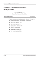
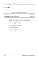
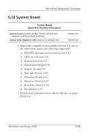
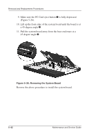
Removal and Replacement Procedures 5.18 System Board System Board Spare Part Number Information System board (includes 64 MB SDRAM, left and right speakers, and left and right brackets) Optical drive alignment rail (included in Hardware kit) 233567-001 234005-001 1. Prepare the computer for disassembly (Section 5.3) and, in the order below, remove the following components: ❏ Mini PCI communications board (Section 5.3) ❏ LED cover (Section 5.6) ❏ Keyboard (Section 5.7) ❏ Optical drive (Section 5.8) ❏ Display (Section 5.9) ❏ Heat sink (Section 5.10) ❏ Processor (Section 5.11) ❏ Top cover (Section 5.12) ❏ Hard drive (Section 5.15) ❏ Fan (Section 5.17) 2. Turn the base enclosure bottom side up with the rear panel facing you. Maintenance and Service Guide 5-39
-
 1
1 -
2
-
3
-
4
-
5
-
6
-
7
-
8
-
9
-
10
-
11
-
12
-
13
-
14
-
15
-
16
-
17
-
18
-
19
-
20
-
21
-
22
-
23
-
24
-
25
-
26
-
27
-
28
-
29
-
30
-
31
-
32
-
33
-
34
-
35
-
36
-
37
-
38
-
39
-
40
-
41
-
42
-
43
-
44
-
45
-
46
-
47
-
48
-
49
-
50
-
51
-
52
-
53
-
54
-
55
-
56
-
57
-
58
-
59
-
60
-
61
-
62
-
63
-
64
-
65
-
66
-
67
-
68
-
69
-
70
-
71
-
72
-
73
-
74
-
75
-
76
-
77
-
78
-
79
-
80
-
81
-
82
-
83
-
84
-
85
-
86
-
87
-
88
-
89
-
90
-
91
-
92
-
93
-
94
-
95
-
96
-
97
-
98
-
99
-
100
-
101
-
 102
102 -
 103
103 -
 104
104 -
 105
105 -
 106
106 -
 107
107 -
 108
108 -
 109
109 -
 110
110 -
 111
111 -
 112
112 -
113
-
114
-
115
-
116
-
117
-
118
-
119
-
120
-
121
-
122
-
123
-
124
-
125
-
126
-
127
-
128
-
129
-
130
-
131
-
132
-
133
-
134
-
135
-
136
-
137
-
138
-
139
-
140
-
141
-
142
-
143
-
144
-
145
-
146
-
147
-
148
-
149
-
150
-
151
-
152
-
153
 |
 |
