HP Evo Notebook PC n110 Compaq Armada 110 and Compaq Evo N110 Maintenance and - Page 71
Disassembly Sequence Chart
 |
View all HP Evo Notebook PC n110 manuals
Add to My Manuals
Save this manual to your list of manuals |
Page 71 highlights
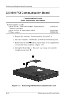
Removal and Replacement Procedures 5.2 Disassembly Sequence Chart Use the chart below to determine the section number to be referenced when removing computer components. Table 5-1 Disassembly Sequence Chart Section 5.3 5.4 5.5 5.6 5.7 5.8 5.9 5.10 5.11 5.12 5.13 5.14 5.15 5.16 5.17 5.18 Description Preparing the computer for disassembly Computer feet Mini PCI Communications Board LED cover Keyboard Optical drive Display Heat sink Processor Top cover Diskette drive TouchPad Hard drive Hard drive bracket Disk cell Real Time Clock (RTC) battery Fan Fan bracket System board Optical drive alignment rail # of Screws Removed 0 0 1 0 2 1 7 5 0 15 2 1 3 0 2 7 Maintenance and Service Guide 5-3
-
 1
1 -
2
-
3
-
4
-
5
-
6
-
7
-
8
-
9
-
10
-
11
-
12
-
13
-
14
-
15
-
16
-
17
-
18
-
19
-
20
-
21
-
22
-
23
-
24
-
25
-
26
-
27
-
28
-
29
-
30
-
31
-
32
-
33
-
34
-
35
-
36
-
37
-
38
-
39
-
40
-
41
-
42
-
43
-
44
-
45
-
46
-
47
-
48
-
49
-
50
-
51
-
52
-
53
-
54
-
55
-
56
-
57
-
58
-
59
-
60
-
61
-
62
-
63
-
64
-
65
-
 66
66 -
 67
67 -
 68
68 -
 69
69 -
 70
70 -
 71
71 -
 72
72 -
 73
73 -
 74
74 -
 75
75 -
 76
76 -
77
-
78
-
79
-
80
-
81
-
82
-
83
-
84
-
85
-
86
-
87
-
88
-
89
-
90
-
91
-
92
-
93
-
94
-
95
-
96
-
97
-
98
-
99
-
100
-
101
-
102
-
103
-
104
-
105
-
106
-
107
-
108
-
109
-
110
-
111
-
112
-
113
-
114
-
115
-
116
-
117
-
118
-
119
-
120
-
121
-
122
-
123
-
124
-
125
-
126
-
127
-
128
-
129
-
130
-
131
-
132
-
133
-
134
-
135
-
136
-
137
-
138
-
139
-
140
-
141
-
142
-
143
-
144
-
145
-
146
-
147
-
148
-
149
-
150
-
151
-
152
-
153
 |
 |

Removal and Replacement Procedures
Maintenance and Service Guide
5–3
5.2 Disassembly Sequence Chart
Use the chart below to determine the section number to be
referenced when removing computer components.
Table 5-1
Disassembly Sequence Chart
Section
Description
# of Screws
Removed
5.3
Preparing the computer for disassembly
0
5.4
Computer feet
0
5.5
Mini PCI Communications Board
1
5.6
LED cover
0
5.7
Keyboard
2
5.8
Optical drive
1
5.9
Display
7
5.10
Heat sink
5
5.11
Processor
0
5.12
Top cover
15
5.13
Diskette drive
2
5.14
TouchPad
1
5.15
Hard drive
Hard drive bracket
3
5.16
Disk cell Real Time Clock (RTC) battery
0
5.17
Fan
Fan bracket
2
5.18
System board
Optical drive alignment rail
7