HP Evo Notebook PC n110 Compaq Armada 110 and Compaq Evo N110 Maintenance and - Page 75
Removing the Mini PCI Communication Board, communication board.
 |
View all HP Evo Notebook PC n110 manuals
Add to My Manuals
Save this manual to your list of manuals |
Page 75 highlights
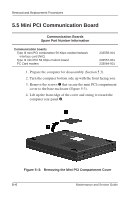
Removal and Replacement Procedures 5. Remove the mini PCI compartment cover. 6. Pull away the plastic retention clips on each side of the mini PCI communication board 1 (Figure 5-4). The board tilts upward. 7. Lift the edge of the board and slide it gently out of the connector 2. Figure 5-4: Removing the Mini PCI Communication Board 8. Place the board in an electrostatic-safe container. Reverse the above procedure to install the mini PCI communication board. Maintenance and Service Guide 5-7
-
 1
1 -
2
-
3
-
4
-
5
-
6
-
7
-
8
-
9
-
10
-
11
-
12
-
13
-
14
-
15
-
16
-
17
-
18
-
19
-
20
-
21
-
22
-
23
-
24
-
25
-
26
-
27
-
28
-
29
-
30
-
31
-
32
-
33
-
34
-
35
-
36
-
37
-
38
-
39
-
40
-
41
-
42
-
43
-
44
-
45
-
46
-
47
-
48
-
49
-
50
-
51
-
52
-
53
-
54
-
55
-
56
-
57
-
58
-
59
-
60
-
61
-
62
-
63
-
64
-
65
-
66
-
67
-
68
-
69
-
 70
70 -
 71
71 -
 72
72 -
 73
73 -
 74
74 -
 75
75 -
 76
76 -
 77
77 -
 78
78 -
 79
79 -
 80
80 -
81
-
82
-
83
-
84
-
85
-
86
-
87
-
88
-
89
-
90
-
91
-
92
-
93
-
94
-
95
-
96
-
97
-
98
-
99
-
100
-
101
-
102
-
103
-
104
-
105
-
106
-
107
-
108
-
109
-
110
-
111
-
112
-
113
-
114
-
115
-
116
-
117
-
118
-
119
-
120
-
121
-
122
-
123
-
124
-
125
-
126
-
127
-
128
-
129
-
130
-
131
-
132
-
133
-
134
-
135
-
136
-
137
-
138
-
139
-
140
-
141
-
142
-
143
-
144
-
145
-
146
-
147
-
148
-
149
-
150
-
151
-
152
-
153
 |
 |

Removal and Replacement Procedures
Maintenance and Service Guide
5–7
5. Remove the mini PCI compartment cover.
6. Pull away the plastic retention clips on each side of the mini
PCI communication board
1
(Figure 5-4). The board tilts
upward.
7. Lift the edge of the board and slide it gently out of the
connector
2
.
Figure 5–4:
Removing the Mini PCI Communication Board
8. Place the board in an electrostatic-safe container.
Reverse the above procedure to install the mini PCI
communication board.