HP J9087A User Manual
HP J9087A Manual
 |
View all HP J9087A manuals
Add to My Manuals
Save this manual to your list of manuals |
HP J9087A manual content summary:
- HP J9087A | User Manual - Page 1
ProCurve Series 2600 Switches PoE Power over Ethernet Devices www.procurve.com Installation and Getting Started Guide - HP J9087A | User Manual - Page 2
- HP J9087A | User Manual - Page 3
ProCurve Series 2600 Switches Installation and Getting Started Guide - HP J9087A | User Manual - Page 4
software on equipment that is not furnished by Hewlett-Packard. Warranty See the Customer Support/Warranty booklet included with the product. A copy of the specific warranty terms applicable to your HewlettPackard products and replacement parts can be obtained from your HP Sales and Service Office - HP J9087A | User Manual - Page 5
the Switch 1-3 Network Ports 1-4 LEDs 1-4 Port LEDs 1-6 Multiple-Display Port LEDs - Port LED View or LED Mode Select Button and Indicator LEDs 1-7 Reset Button 1-9 Clear Button 1-9 Back of the Switch 1-10 Console Port 1-11 Power Connector 1-11 Switch Features 1-11 2 Installing the Switch - HP J9087A | User Manual - Page 6
Screen 3-2 Where to Go From Here 3-4 Using the IP Address for Remote Switch Management 3-5 Starting a Telnet Session 3-5 Starting a Web Browser Session 3-5 4 Troubleshooting Basic Troubleshooting Tips 4-1 Diagnosing with the LEDs 4-4 Proactive Networking 4-8 Hardware Diagnostic Tests 4-9 iv - HP J9087A | User Manual - Page 7
Network Communications 4-10 Testing End-to-End Network Communications 4-10 Restoring the Factory Default Configuration 4-11 Downloading New Switch Software 4-12 HP Customer Support Services 4-12 Before Calling Support 4-12 A Switch Specifications Physical A-1 Electrical A-1 Environmental - HP J9087A | User Manual - Page 8
sicurezza C-4 Consideraciones sobre seguridad C-5 Safety Information (Japan C-6 Safety Information (China C-7 EMC Regulatory Statements C-8 U.S.A C-8 Canada C-8 Australia/New Zealand C-8 Japan C-8 Korea C-9 Taiwan C-9 European Community C-10 Waste Electrical and Electronic Equipment - HP J9087A | User Manual - Page 9
M 12 14 (all 10/100Base-TX ports are HP Auto-MDIX, Gig-T ports are IEEE Auto MDI/MDI-X) MiniGBIC Ports 24 ! Use only one (T or M) for each Gigabit port Power Fault ProCurve Switch 2600-PWR J8762A PoE Status RPS Act EPS LED Mode FDx Fan Spd * Test PoE Reset Clear *Spd mode: off = 10 - HP J9087A | User Manual - Page 10
devices. For further information regarding PoE power, see the PoE Planning and Implementation Guide which is on the documentation CD that came with the switch. ■ Redundant and External Power Supply Support - The Series 2600PWR Switches can be connected to a ProCurve 600 Redundant and External Power - HP J9087A | User Manual - Page 11
) Power and Fault LEDs RPS, EPS, Fan and Test Status LEDs Console Port ProCurve Switch 2600-8-PWR Switch port LEDs Power Fault ProCurve Switch 2600-PWR J8762A PoE Status RPS Act EPS LED Mode FDx Fan Spd * Test PoE Reset Clear *Spd mode: off = 10 Mbps, flash = 100 Mbps, on = 1000 - HP J9087A | User Manual - Page 12
the switch. ■ Dual-personality ports. You can use either the 10/100/1000Base-T RJ-45 connector, or install a supported ProCurve mini-GBIC for fiber-optic connections. The RJ-45 connectors support the IEEE Auto MDI/MDI-X feature, which operates the same as the "HP Auto-MDIX" feature. By default, the - HP J9087A | User Manual - Page 13
600 RPS/EPS or an 610 EPS, and receiving PoE power. The External Power Supply has experienced a fault: • PoE power is oversubscribed (not enough PoE power available). • The software on the ProCurve Series 2600-PWR Switches may not support the EPS function. • There is a fan, overcurrent, power supply - HP J9087A | User Manual - Page 14
network cable is connected to the port • the port is not receiving link beat or sufficient light • the port has been disabled through the switch console, the web browser interface, ProCurve Manager, or other network management tool. The port has failed self test. The switch Fault, and Self Test LEDs - HP J9087A | User Manual - Page 15
view mode to the next. The default view is Activity (Act). Switch 2626-PWR and 2650-PWR Link LED (port number) Mode LED Power Fault hp procurve 1 3 5 7 switch 2650-PWR 2 1 4 6 8 J8165A PoE Status RPS Act EPS LED Mode FDx Fan Spd Test PoE Reset Clear 2 Spd mode: off = 10 - HP J9087A | User Manual - Page 16
Introducing the Switch Front of the Switch Table 1-3. Multiple-Display Port LEDs Switch LEDs State Meaning Switch 2626 and Switch 2650 Port LED View Lnk indicator LEDs (4 green LEDs) Act FDx Spd Indicates that the Port LEDs are displaying link information: • if the Port LED is on, the port is - HP J9087A | User Manual - Page 17
, the web browser interface, and SNMP management are removed, and the factory default configuration is restored to the switch. For the specific method to restore the factory default configuration, see "Restoring the Factory Default Configuration" on page 11, "Troubleshooting" of this manual. 1-9 - HP J9087A | User Manual - Page 18
connector Cooling vent - make sure this is not obstructed for proper switch operation ProCurve Switch 2626-PWR and 2650-PWR Console EPS Input HP ProCurve RPS Input 12V 7.5A Console Port EPS Input RPS Input EPS Redundant Input EPS Input Line 50/60 Hz. 100-240 V~ 7.5 A AC power connector - HP J9087A | User Manual - Page 19
with your switch. ■ The 2600-8-PWR switch supports some pre-standard PoE devices, for a current list see the FAQ page for the 2600-8-PWR Switch, which can be found on the ProCurve Web site, http://www.procurve.com, Technical Support, FAQs (all). ■ plug-and-play networking-all ports are enabled - HP J9087A | User Manual - Page 20
end nodes into logical groupings that fit your business needs. ■ support for many advanced features to enhance network performance- for a description, see the Management and Configuration Guide, which is on the Documentation CD-ROM included with your switch. ■ download of new switch software - HP J9087A | User Manual - Page 21
Parts The Series 2600 Switches have the following components: ■ ProCurve Series 2600 Switches Installation and Getting Started Guide (5991-2165), this manual ■ ProCurve Manager - CD ROM and booklet ■ Console cable ■ Customer Support/Warranty booklet ■ Accessory kits Switches 2626 and 2650 Non - HP J9087A | User Manual - Page 22
Installing the Switch Included Parts ■ AC power cord, one of the following: Non-PWR Switches PWR Switches 1 and 2600-8-PWR Australia/New Zealand China Continental Europe Denmark Japan Switzerland United Kingdom/Hong Kong/Singapore United States/Canada/Mexico South Africa Thailand Taiwan 8120- - HP J9087A | User Manual - Page 23
using a web browser, from an SNMP network management station, or through a Telnet session. Configuration changes can be made by using the included console cable to connect a PC to the switch's console port. At this point, your switch is fully installed. See the rest of this chapter if you need - HP J9087A | User Manual - Page 24
the Switch Installing the Switch Installation Procedures Installation Precautions Follow these precautions when installing your ProCurve Series 2600 Switches. WARNING ■ The rack or cabinet should be adequately secured to prevent it from becoming unstable and/or falling over. Devices installed in - HP J9087A | User Manual - Page 25
-pair cables for connecting to any network devices including end nodes, such as computers, or to other switches, hubs, and routers. Note: For 1000 Mbps operation, all four wire pairs are used for data transmission, therefore PoE is not supported for 1000 Mbps operation. Installing the Switch 2-5 - HP J9087A | User Manual - Page 26
Installing the Switch Installing the Switch Installation Procedures Port Type Cable Type Length Limits cables as for • 70 kilometers Gigabit-LX. Note: Gigabit-LH - Between the transmit and receive ends of the cable, at least 5db of attenuation is required for a reliable connection. This is - HP J9087A | User Manual - Page 27
only supported genuine ProCurve mini-GBICs with your switch. NonProCurve mini-GBICs are not supported, and their use may result in product malfunction. Should you require additional ProCurve mini-GBICs, contact your ProCurve Networking Sales and Service Office or authorized dealer. Installing the - HP J9087A | User Manual - Page 28
Installing the Switch Installation Procedures Removing the mini-GBICs Note You should disconnect the network cable from the mini-GBIC before removing it from the switch. Depending on when you purchased your ProCurve mini-GBIC, it may have either of three different release mechanisms: a plastic tab - HP J9087A | User Manual - Page 29
power cord to the power connector 2626 PWR and 2650 PWR switches Console EPS Input HP ProCurve RPS Input 12V 7.5A Line 50/60 Hz. 100-240 V~ 7.5 A Connect power cord to the power connector The Series 2600 Switches do not have a power switch. They are powered on when the power cord is connected - HP J9087A | User Manual - Page 30
LED Switch port LEDs Switch 2650 Installing the Switch Power and Fault LEDs When the switch is powered on, it performs its diagnostic self test. Self test takes approximately 50 seconds to complete. Switch 2650-PWR Power Fault hp procurve 1 3 5 7 switch 2650-PWR 2 1 4 6 8 J8165A PoE - HP J9087A | User Manual - Page 31
the Port LED View or LED Mode selected. For the non-PWR switches, in the default view mode (Link), the LEDs should be on. For the PWR switches, not completed correctly. Refer to chapter 4, "Troubleshooting" for diagnostic help. 4. Mount the Switch After the switch passes self test, it is ready to be - HP J9087A | User Manual - Page 32
cabinet in place of the 12-24 screws that are supplied with the switch. Rack Mounting the 2626-PWR and 2650-PWR switches 1. Use a #1 Phillips (cross-head) screwdriver and attach the mounting brackets to the switch with the included 8-mm M4 screws. Installing the Switch WARNING For safe reliable - HP J9087A | User Manual - Page 33
Installing the Switch Installation Procedures The mounting brackets have multiple mounting holes and can be rotated allowing for a wide variety of mounting options. These include mounting the switch as shown in the illustration above. 2. Hold the switch with attached brackets up to the rack and move - HP J9087A | User Manual - Page 34
1. Use a #1 Phillips (cross-head) screwdriver and attach the mounting brackets to the switch with the included 8-mm M4 screws. Installing the Switch 8 mm M4 screws Note WARNING The mounting brackets have multiple mounting holes and can be rotated allowing for a wide variety of mounting options - HP J9087A | User Manual - Page 35
Installing the Switch Installing the Switch Installation Procedures 2. Hold the switch with attached brackets up to the rack and move it vertically until rack holes line up with the bracket holes, then insert and tighten the four number 12-24 screws holding the brackets to the rack. Install 12-24 - HP J9087A | User Manual - Page 36
because of the size and weight of the devices. Wall mounting the 2600-8-PWR switch is supported. See page 2-18 for instructions. For safe operation do not install the switch with the back face of the switch (with the fan vents) facing either downward or upward. Do not wall mount the 2626-PWR - HP J9087A | User Manual - Page 37
wood screws (not included). For "Flat" Wall Mounting (Vertical) M4 screws Wall 5/8-inch wood screws Installing the Switch WARNING The brackets are attached on opposite corners to improve the stability of the switch on the wall. The Switch 2626-PWR or 2650-PWR Switches are not wall mountable. 2-17 - HP J9087A | User Manual - Page 38
Installing the Switch Installing the Switch Installation Procedures Wall mounting the Series 2600-8-PWR Switch 1. Use a #1 Phillips (cross-head) screwdriver and attach the mounting brackets to the switch with the included 8-mm M4 screws. 2. Attach the switch to the wall or wood surface with two - HP J9087A | User Manual - Page 39
Caution Installing the Switch Installation Procedures Horizontal Surface Mounting Place the switch on a table or other horizontal surface. The switch comes with rubber feet in the accessory kit that can be used to help keep the switch from sliding on the surface. Attach the rubber feet to the four - HP J9087A | User Manual - Page 40
, an end node) is at the other end of the cable. If the Link LED does not go on when the network cable is connected to the port, see "Diagnosing With the LEDs" in chapter 4, "Troubleshooting". To disconnect: Press the small tab on the plug and pull the plug out of the port. hp procurve switch 2650 - HP J9087A | User Manual - Page 41
is additional power made available to the switch's ports. For further information regarding the 600 RPS/EPS PoE capabilities, see the PoE Planning and Implementation Guide and the ProCurve 600/610 External Power Supplies Installation and Getting Started Guide, which is on the Documentation CD-ROM - HP J9087A | User Manual - Page 42
the end devices connected to the switch ports may not receive power if an internal switch PoE power supply should fail. For further information regarding the 600 RPS/EPS PoE capabilities, see the PoE Planning and Implementation Guide and the ProCurve 600/610 External Power Supplies Installation and - HP J9087A | User Manual - Page 43
Installing the Switch Installing the Switch Installation Procedures 600 RPS/EPS LEDs The 600 RPS one connected device. Lowest-numbered port has priority. R3 R4 RPS 3 RPS 4 RPS 5 R5 RPS 6 ! EPS Power: 50V 370W total for PoE applications. Power is shared when both ports are used. R6 E1 EPS - HP J9087A | User Manual - Page 44
. Power is shared when both ports are used. R6 E1 EPS 1 EPS 2 E2 Device Connected Power Status Line: 50/60 Hz. 10 0 - 240 V~ 9.1A (9,1A) Console EPS Input HP ProCurve RPS Input 12V 7.5A Switch RPS output port Line 50/60 Hz. 100-240 V~ 7.5 A RPS input port Installing the Switch 2-24 - HP J9087A | User Manual - Page 45
Procedures The following illustration shows an example of connectivity between an RPS/ EPS device and six switch devices as a redundant AC power supply. 2650-PWR switches Installing the Switch Highest priority connected to port 1 600 RPS/EPS The 600 RPS/EPS can provide backup power for up to six - HP J9087A | User Manual - Page 46
for PoE applications. Power is shared when both ports are used. R6 E1 EPS 1 EPS 2 E2 Device Connected Power Status Line: 50/60 Hz. 100 -240 V~ 9.1A (9,1A) Switch EPS output Console EPS Input HP ProCurve RPS Input 12V 7.5A EPS input port Line 50/60 Hz. 100-240 V~ 7.5 A Installing the - HP J9087A | User Manual - Page 47
Installing the Switch 610 EPS LEDs Installing the Switch Installation Procedures Power and Fault LEDs Backup Power Port LEDs EPS Port LEDs 610 EPS hp procurve 610 eps J8169A Pow er Fault Internal Power Status Fan/Temp Status Fan/Temp Status flash = Temperature too high Fan/Temp Status + - HP J9087A | User Manual - Page 48
Installing the Switch Installation Procedures 50 V 16 A 50 V 16 A RPS 12 V 7.5 A RPS 12 V 7.5 A Line: 50/60 Hz. 100-240 V~ 7.5 A Line: 50/60 Hz. 100-240 V~ 7.5 A hp procurve 610 eps J8169A Pow er Fault Internal Power Status Fan/Temp Status Fan/Temp Status flash = Temperature too high Fan/Temp - HP J9087A | User Manual - Page 49
A RPS 12 V 7.5 A RPS 12 V 7.5 A RPS 12 V 7.5 A RPS 12 V 7.5 A Installing the Switch Installation Procedures Line: 50/60 Hz. 100-240 V~ 7.5 A Line: 50/60 Hz. 100-240 V~ 7.5 A Line: 50/60 Hz. 100-240 V~ 7.5 A Line: 50/60 Hz. 100-240 V~ 7.5 A hp procurve 610 eps J8169A Pow er Fault Internal Power - HP J9087A | User Manual - Page 50
■ read the event log and access diagnostic tools to help in troubleshooting ■ download new software to the switch ■ add passwords to control access to the switch from the console, web browser interface, and network management stations The console can be accessed through these methods: ■ Out-of - HP J9087A | User Manual - Page 51
, for example: ProCurve Switch # If you want to continue with console management of the switch at this time, see chapter 3, "Getting Started With Switch Configuration" for some basic configuration steps. For more detailed information, refer to the Management and Configuration Guide, which is on - HP J9087A | User Manual - Page 52
Installing the Switch Installing the Switch Sample Network Topologies for Non-PWR Switches Sample Network Topologies for Non-PWR Switches This section shows a few sample network topologies in which the Switch 2650 is implemented. For more topology information, see the ProCurve networking products - HP J9087A | User Manual - Page 53
Twisted-pair straight-through or crossover cables to hubs Switch 2650 Switch 2650 Installing the Switch Twisted-pair straight-through cables to end nodes PCs, printers, and local servers The Series 2600 Switches also work well as segment switches. That is, with their high performance, they can - HP J9087A | User Manual - Page 54
Installing the Switch Installing the Switch Sample Network Topologies for Non-PWR Switches Because the Series 2600 Switches have the "HP Auto-MDIX" and "IEEE Auto MDI/MDI-X" features, the connections between the switch and the hubs, and between the switch and end match in specification. 2-34 - HP J9087A | User Manual - Page 55
backbone Installing the Switch Switch 5308xl Gigabit fiber-optic cables Switch 2650 Switch 2650 Switch 2650 Switch 2650 Note The simpler desktop and segment networks shown in the previous two examples can easily be combined and expanded. For example, you could use an ProCurve Switch 5308xl - HP J9087A | User Manual - Page 56
the Series 2600-PWR Switches. For more topology information, see the ProCurve networking products Web site, http://www.procurve.com. As a Desktop Switch Implementing PoE 600 RPS/EPS Twisted-pair straight-through or crossover cables 2650-PWR Server Installing the Switch Wireless Access Point IP - HP J9087A | User Manual - Page 57
P orts (1 - 8) - (Ports are HP A uto-MDIX) Link 1 Mode 2 3 4 Link 5 Mode 6 7 8 Dual-Personality P ort: 10/1 00/1 000-T (T) o r Mini-GBIC (M) (P ort 9T is IEEE A uto MDI/MDIX) Link 9T Mode 9M Link Mode ! Use only one (T or M) f or Port 9 Switch 2650-PWR Installing the Switch Wireless - HP J9087A | User Manual - Page 58
Installing the Switch Installing the Switch Sample Network Topologies for PWR Switches Connecting to a Backbone Switch Implementing PoE To Gigabit-Ethernet backbone Switch 5308xl Gigabit fiber-optic cable Switch 2650 non-PWR Switch 2650-PWR Switch 2650 600 RPS/EPS Switch 2650-PWR Wireless - HP J9087A | User Manual - Page 59
Installing the Switch Installing the Switch Sample Network Topologies for PWR Switches Stacking the Switch Switch 2600 and 2600-PWR Series devices can be connected together, through standard network connections, and managed through a single IP address. Up to 16 switches can be connected together in - HP J9087A | User Manual - Page 60
- This page is intentionally unused. - - HP J9087A | User Manual - Page 61
interface, please see the Management and Configuration Guide, which is on the Documentation CD-ROM that came with your switch. Recommended Minimal Configuration In the factory default configuration, the switch has no IP (Internet Protocol) address and subnet mask, and no passwords. In this state, it - HP J9087A | User Manual - Page 62
for example: ProCurve# 2. At the prompt, enter the setup command to display the Switch Setup screen. The following illustration shows the Setup screen with the default settings. 2005 Configuring the Switch 3. Use the [Tab] key to select the Manager Password field and enter a manager password of up - HP J9087A | User Manual - Page 63
and Configuration Guide, which is on the Documentation CD-ROM that came with your switch: Parameter Default System Name blank Optional; up to 25 characters, including spaces System Contact blank Optional; up to 48 characters, including spaces Manager Password blank Recommended; up - HP J9087A | User Manual - Page 64
on the Series 2600 Switches, see the Management and Configuration Guide, which is on the Documentation CD-ROM that came with your switch. To Recover from a Lost Manager Password: If you cannot start a console session at the manager level because of a lost Manager password, you can clear all - HP J9087A | User Manual - Page 65
the switch console command (CLI) prompt, for example: ProCurve# Enter Switches can be managed through a graphical interface that you can access from any PC or workstation on the network by running your web browser and typing in the switch's IP address as the URL. No additional software installation - HP J9087A | User Manual - Page 66
interface, please see the Management and Configuration Guide, which is on the Documentation CD-ROM that came with your switch. An extensive help system is also available for the web browser interface. To access the help system though, the subnet on which the switch is installed must have access to - HP J9087A | User Manual - Page 67
■ hardware diagnostic tests (page 4-9) ■ restoring the factory default configuration (page 4-11) ■ downloading new software to the Series 2600 Switches (page 4-12) ■ HP Customer Support Services (page 4-12) Basic Troubleshooting Tips Most problems are caused by the following situations. Check for - HP J9087A | User Manual - Page 68
multiple network cables to be used for a single network connection without causing a data path loop. For more information on Spanning Tree and Trunking, see the Management and Configuration Guide, which is on the Documentation CD-ROM that came with your switch. Troubleshooting 4-2 - HP J9087A | User Manual - Page 69
that may be affecting the port. For more information, see the Management and Configuration Guide, which is on the Documentation CD-ROM that came with your switch. For more information on possible network problems and their solutions, refer to the technical note "Troubleshooting LAN Performance and - HP J9087A | User Manual - Page 70
Troubleshooting Diagnosing with the LEDs Diagnosing with the LEDs Table 4-1 shows LED patterns on the switch and the switch modules that indicate problem conditions. 1. Check in the table for the LED pattern you see on your switch 1 Off 1 On, but the port is not ➐ communicating On Blinking - HP J9087A | User Manual - Page 71
switch should be replaced. Contact your HP-authorized LAN dealer, or use the electronic support services from HP to get assistance. See the Customer Support/Warranty booklet for more information. ➎ The network port Try power cycling the switch. If the fault indication reoccurs, the switch port - HP J9087A | User Manual - Page 72
Troubleshooting Diagnosing with the LEDs Tip Problem Solution ➏ The network Try the following procedures: connection is not • For the indicated port, verify that both ends of the cabling, at the switch and the working connected device, are connected properly. properly. • Verify the - HP J9087A | User Manual - Page 73
to see how the port is configured for these features. For software troubleshooting tips, see the chapter "Troubleshooting" in the Management and Configuration Guide, which is on the Documentation CD-ROM that came with your switch. Ensure also, that the device at the other end of the connection is - HP J9087A | User Manual - Page 74
is provided with your switch. The console interface is also accessible through a Telnet connection. For more information on using these software tools to diagnose and manage your switch, see the "Troubleshooting" chapter in the Management and Configuration Guide, which is on the Documentation - HP J9087A | User Manual - Page 75
Troubleshooting Hardware Diagnostic Tests Hardware Diagnostic Tests Testing the Switch by Resetting It If you believe the switch is not operating correctly, you can reset the switch to test its circuitry and operating code. To reset a switch, either: ■ unplug and plug in the power cord (power - HP J9087A | User Manual - Page 76
interface. For more information, see the Management and Configuration Guide, which is on the Documentation CD-ROM that came with your switch. Testing End-to-End Network Communications Both the switch and the cabling can be tested by running an end-to-end communications test-a test that sends known - HP J9087A | User Manual - Page 77
factory default reset. Then, after the reset and resolution of the original problem, you can restore the saved configuration to the switch. For both the save and restore processes, you can use the console copy command. For more information on this command, see the Management and Configuration Guide - HP J9087A | User Manual - Page 78
, see the Management and Configuration Guide, which is on the Documentation CDROM that came with your switch. The new switch software would be available on the ProCurve Web site, http://www.procurve.com. HP Customer Support Services If you are still having trouble with your switch, Hewlett-Packard - HP J9087A | User Manual - Page 79
Switch Specifications A Switch Specifications Physical 2600 Non-PWR Series 2626 (J4900B) 2650 (J4899B) Width 44.3 cm (17.4 in) 44.3 cm (17.4 in -1.7A 7.5A-3.5A 7.5A-3.5A 50/60 Hz 50/60 Hz 50/60 Hz The switch automatically adjusts to any voltage between 100-240 volts and either 50 or 60 Hz. A-1 - HP J9087A | User Manual - Page 80
Switch Specifications Switch Specifications Environmental Non-PWR 2600 Series Operating Non-Operating Temperature 0 °C to 55 °C -PWR 2288 921 2626 Non-PoE 341 2650 Non-PoE 341 1 Includes switch and maximum number of PoE powered devices connected to the switch at 15.4 watts. Acoustic - HP J9087A | User Manual - Page 81
Switch Specifications Switch Specifications Connectors ■ The 10/100/1000 Mbps RJ-45 twisted-pair ports are compatible with the following standards: • IEEE 802.3ab 1000Base-T • IEEE 802.3u 100Base-TX • IEEE 802.3 10Base-T ■ The 1000 Mbps LC fiber-optic ports on the Gigabit-SX and Gigabit-LX miniGBIC - HP J9087A | User Manual - Page 82
- This page is intentionally unused. - - HP J9087A | User Manual - Page 83
minimum pin-out information and specifications for twisted-pair cables. Incorrectly wired cabling is the most common cause of problems for LAN communications. HP recommends that you work with a qualified LAN cable installer for assistance with your cabling requirements. Switch Ports The fixed RJ-45 - HP J9087A | User Manual - Page 84
that connect the switch and other end devices to the patch panels on your site. The patch cables are frequently overlooked when testing cable and they must also comply with the cabling standards. Fiber-Optic Cables Port Type Gigabit-SX Gigabit-LX Gigabit-LH Cable Specifications Connector Type - HP J9087A | User Manual - Page 85
CRC or FCS errors, you may need to install one of these patch cords between the Gigabit-LX port in your switch and your multimode fiberoptic network cabling, and between the Gigabit-LX transmission device and the network cabling at the other end of the multimode fiber-optic cable run. A patch - HP J9087A | User Manual - Page 86
Tx Switch Ports and Network Cables Mode Conditioning Patch Cord for Gigabit-LX Installing the Patch Cord As shown in the illustration below, connect the patch cord to the Gigabit-LX mini-GBIC with the section of single-mode fiber plugged in to the Tx (transmit) port. Then, connect the other end of - HP J9087A | User Manual - Page 87
HP Auto-MDIX Feature: In the default configuration, "Auto", the fixed 10/100Base-TX ports on the Series 2600 Switches all automatically detect the type of port be used for any of the connections. (The 10/100/1000-T ports support the IEEE 802.3ab standard, which includes the "Auto MDI/MDI-X" feature - HP J9087A | User Manual - Page 88
Switch Ports and Network Cables Switch Ports and Network Cables Twisted-Pair Cable/Connector Pin-Outs ■ For 100 Mbps connections to the ports, use 100-ohm Category 5 UTP or STP cable only, as supported by the IEEE 802.3u Type 100Base-TX standard. ■ For 1000 Mbps connections, 100-ohm Category 5e or - HP J9087A | User Manual - Page 89
Straight-through Twisted-Pair Cable for 10 Mbps or 100 Mbps Network Connections Because of the HP Auto-MDIX operation of the 10/100 ports on the switch, for all network connections, to PCs, servers or other end nodes, or to hubs or other switches, you can use straight-through cables. If any of these - HP J9087A | User Manual - Page 90
Mbps or 100 Mbps Network Connection The HP Auto-MDIX operation of the 10/100 ports on the switch also allows you to use crossover cables for all network connections, to PCs, servers or other end nodes, or to hubs or other switches. If any of these ports are given a fixed configuration, for example - HP J9087A | User Manual - Page 91
-Through Twisted-Pair Cable for 1000 Mbps Network Connections 1000Base-T connections require that all four pairs of wires be connected. Cable Diagram Switch Ports and Network Cables Note . Pins 1 and 2 on connector "A" must be wired as a twisted pair to pins 1 and 2 on connector "B". Pins 3 and - HP J9087A | User Manual - Page 92
- This page is intentionally unused. - - HP J9087A | User Manual - Page 93
manual denotes a hazard that can cause injury or death. A Caution in the manual Servicing There are no user-serviceable parts inside these products. Any servicing, adjustment, maintenance, or repair must be performed only by service-trained personnel. These products do not have a power switch - HP J9087A | User Manual - Page 94
de classe I et possède une borne de mise à la terre. La source d'alimentation principale doit être munie d'une prise de terre de sécurité installée aux bornes du câblage d'entrée, sur le cordon d'alimentation ou le cordon de raccordement fourni avec le produit. Lorsque cette protection semble avoir - HP J9087A | User Manual - Page 95
Safety and EMC Regulatory Statements Hinweise zur Sicherheit Hinweise zur Sicherheit ! WARNING Caution Symbol für Dokumentationsverweis. Wenn das Produkt mit diesem Symbol markiert ist, schlagen Sie bitte in der Produktdokumentation nach, um mehr Informationen über das Produkt zu erhalten. Eine - HP J9087A | User Manual - Page 96
Safety and EMC Regulatory Statements Considerazioni sulla sicurezza Considerazioni sulla sicurezza ! WARNING Caution Simbolo di riferimento alla documentazione. Se il prodotto è contrassegnato da questo simbolo, fare riferimento alla documentazione sul prodotto per ulteriori informazioni su di - HP J9087A | User Manual - Page 97
Safety and EMC Regulatory Statements Consideraciones sobre seguridad Consideraciones sobre seguridad ! WARNING Caution Símbolo de referencia a la documentación. Si el producto va marcado con este símbolo, consultar la documentación del producto a fin de obtener mayor información sobre el producto - HP J9087A | User Manual - Page 98
Safety and EMC Regulatory Statements Safety Information (Japan) Safety Information (Japan) Japan Power Cord Warning C-6 Safety and EMC Regulatory Statements - HP J9087A | User Manual - Page 99
Safety and EMC Regulatory Statements Safety Information (China) Safety Information (China) C-7 Safety and EMC Regulatory Statements - HP J9087A | User Manual - Page 100
not installed and used in accordance with the instruction manual, may cause interference to radio communications. Operation of this equipment in a residential area may cause interference in which case the user will be required to correct the interference at his own expense. Canada - HP J9087A | User Manual - Page 101
Korea Safety and EMC Regulatory Statements EMC Regulatory Statements Taiwan Safety and EMC Regulatory Statements C-9 - HP J9087A | User Manual - Page 102
U.S.A. declares that the product: Product Name: HP ProCurve Switch 2650, HP ProCurve Switch 2626 Model Numbers: J4899A, J4899B; J4900A, J4900B Accessories: J4858A, J4859A, J4860A Regulatory Model Number: RSVLC-0204 conforms to the following Product Specifications: Safety: EN60950 (1992) +A1,A2,A3 - HP J9087A | User Manual - Page 103
accordingly. 1) J8169A for use with ProCurve Switch 2626-PWR, 2650-PWR, and RSVLC-0302 Tested with Hewlett-Packard Co. products only. Roseville, July 28, 2005 Mike Avery, Regulatory Engineering Manager European Contact: Your local Hewlett-Packard Sales and Service Office or Hewlett-Packard GmbH - HP J9087A | User Manual - Page 104
more information about where you can drop off your waste equipment for recycling, please contact your local city office, your household waste disposal service or the shop where you purchased the product. Likvidace zařízení soukromými domácími uživateli v Evropské unii Tento symbol na produktu nebo - HP J9087A | User Manual - Page 105
d'informations sur les centres de collecte et de recyclage des appareils mis au rebut, veuillez contacter les autorités locales de votre région, les services de collecte des ordures ménagères ou le magasin dans lequel vous avez acheté ce produit. Entsorgung von Altgeräten aus privaten Haushalten in - HP J9087A | User Manual - Page 106
Safety and EMC Regulatory Statements Waste Electrical and Electronic Equipment (WEEE) Statements Smaltimento delle apparecchiature da parte di privati nel territorio dell'Unione Europea Questo simbolo presente sul prodotto o sulla sua confezione indica che il prodotto non può essere smaltito insieme - HP J9087A | User Manual - Page 107
o ambiente e a saúde das pessoas. Para obter mais informações sobre locais que reciclam esse tipo de material, entre em contato com o escritório da HP em sua cidade, com o serviço de coleta de lixo ou com a loja em que o produto foi adquirido. Likvidácia vyradených zariadení v domácnostiach v Eur - HP J9087A | User Manual - Page 108
- This page is intentionally unused. - - HP J9087A | User Manual - Page 109
address ... 3-3 manager password ... 3-2 subnet mask ... 3-3 Switch Setup screen ... 3-2 basic troubleshooting tips ... 4-1 blinking LEDs error indications ... 4-4 Bootp automatic switch configuration ... 3-2 for in-band access ... 2-30 BTU ratings ... A-2 buttons Clear button ... 1-9 Reset button - HP J9087A | User Manual - Page 110
manually ... 3-2 manager password ... 3-2 restoring factory defaults ... 1-9, 4-11 subnet mask ... 3-3 Switch Setup screen ... 3-2 connecting the switch to a power source ... 2-19 connecting the switch to an EPS ... 2-27-2-28 connecting the switch to an RPS/EPS ... 2-24-2-26 connector specifications - HP J9087A | User Manual - Page 111
used with ... B-2 Gigbit-LX ports, cables used with ... B-2 H horizontal surface mounting switch on ... 2-19 HP Auto-MDIX feature description ... B-5 I in-band ... 3-1 in-band console access types of ... 2-30 included parts ... 2-1 installation connecting the switch to a power source ... 2-19 - HP J9087A | User Manual - Page 112
button ... 3-4 if you lose the password ... 3-4 passwords, deleting ... 1-9 physical specifications, switch ... A-1 Ping test ... 4-10 4 - Index pin-outs twisted-pair cables ... B-5 port configuration checking when troubleshooting ... 4-3 port LEDs description ... 1-6 normal operation ... 2-11 - HP J9087A | User Manual - Page 113
resetting the switch factory default reset ... 4-11 location of Reset button ... 1-9 troubleshooting procedure ... 4-9 RPS/EPS ... 2-21 cables ... 2-22 connecting to a switch ... 2-24-2-26 operation ... 2-22 S safety and regulatory statements ... C-1 safety specifications ... A-3 segment switch - HP J9087A | User Manual - Page 114
link test ... 4-10 Ping test ... 4-10 Proactive Network tools ... 4-8 restoring factory default configuration ... 4-11 testing connections to other devices ... 4-10 testing end-to-end communications ... 4-10 testing the switch ... 4-9 testing the twisted-pair cables ... 4-10 twisted-pair cable cross - HP J9087A | User Manual - Page 115
- HP J9087A | User Manual - Page 116
-Packard Development Company, L.P. Reproduction, adaptation, or translation without prior written permission is prohibited except as allowed under the copyright laws. Printed in Taiwan January 2008 Manual Part Number 5991-2165 *5991-2165*
-
 1
1 -
 2
2 -
 3
3 -
 4
4 -
 5
5 -
 6
6 -
 7
7 -
8
-
9
-
10
-
11
-
12
-
13
-
14
-
15
-
16
-
17
-
18
-
19
-
20
-
21
-
22
-
23
-
24
-
25
-
26
-
27
-
28
-
29
-
30
-
31
-
32
-
33
-
34
-
35
-
36
-
37
-
38
-
39
-
40
-
41
-
42
-
43
-
44
-
45
-
46
-
47
-
48
-
49
-
50
-
51
-
52
-
53
-
54
-
55
-
56
-
57
-
58
-
59
-
60
-
61
-
62
-
63
-
64
-
65
-
66
-
67
-
68
-
69
-
70
-
71
-
72
-
73
-
74
-
75
-
76
-
77
-
78
-
79
-
80
-
81
-
82
-
83
-
84
-
85
-
86
-
87
-
88
-
89
-
90
-
91
-
92
-
93
-
94
-
95
-
96
-
97
-
98
-
99
-
100
-
101
-
102
-
103
-
104
-
105
-
106
-
107
-
108
-
109
-
110
-
111
-
112
-
113
-
114
-
115
-
116
 |
 |
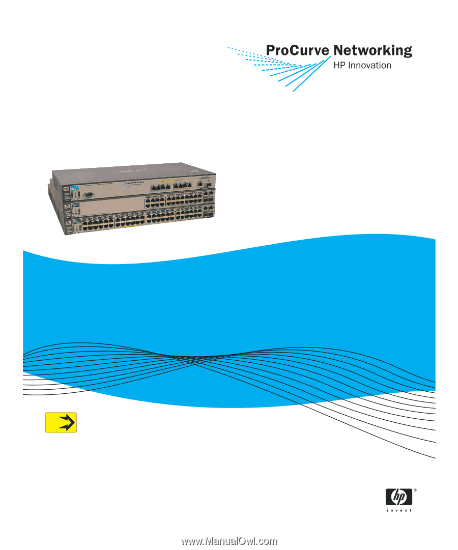
Installation and
Getting Started Guide
www.procurve.com
ProCurve Series
2600 Switches
PoE
Power over Ethernet Devices