HP J9087A User Manual - Page 15
Multiple-Display Port LEDs - Port LED View or LED Mode Select Button and Indicator LEDs
 |
View all HP J9087A manuals
Add to My Manuals
Save this manual to your list of manuals |
Page 15 highlights
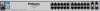
Introducing the Switch Introducing the Switch Front of the Switch Multiple-Display Port LEDs - Port LED View or LED Mode Select Button and Indicator LEDs To optimize the amount of information that can be displayed for each of the switch ports in the limited space available, the Series 2600 Switches use multiple-display LEDs for each port. For the non-PWR switches, there is a single LED per port. The operation of this LED is controlled by the Port LED View select button, and the current setting is indicated by the Port LED View indicator LEDs near the button. Press the button to step from one view mode to the next. The default view is Link (Lnk). Switch 2626 and Switch 2650 Port LED (one for each port) Port LED View select button and indicator LEDs For the PWR switches, there are two LEDs per port. The Link status is always shown by the Link LED. The operation of the Mode LED is controlled by the LED Mode select button, and the current setting is indicated by the LED Mode indicator LEDs near the button. Press the button to step from one view mode to the next. The default view is Activity (Act). Switch 2626-PWR and 2650-PWR Link LED (port number) Mode LED Power Fault hp procurve 1 3 5 7 switch 2650-PWR 2 1 4 6 8 J8165A PoE Status RPS Act EPS LED Mode FDx Fan Spd Test PoE Reset Clear 2 Spd mode: off = 10 Mbps, flash = 100 Mbps, 9 10 on = 1000 LED Mode select button and indicator LEDs For the 2600-8-PWR switch, the LEDs are embedded in the port connector. The Link and Mode LEDs operate the same as the other PWR switches (see above). LED Mode select button and indicator LEDs Switch 2600-8-PWR Mode LED (Right LED) Link LED (Left LED) 1-7
-
 1
1 -
2
-
3
-
4
-
5
-
6
-
7
-
8
-
9
-
 10
10 -
 11
11 -
 12
12 -
 13
13 -
 14
14 -
 15
15 -
 16
16 -
 17
17 -
 18
18 -
 19
19 -
 20
20 -
21
-
22
-
23
-
24
-
25
-
26
-
27
-
28
-
29
-
30
-
31
-
32
-
33
-
34
-
35
-
36
-
37
-
38
-
39
-
40
-
41
-
42
-
43
-
44
-
45
-
46
-
47
-
48
-
49
-
50
-
51
-
52
-
53
-
54
-
55
-
56
-
57
-
58
-
59
-
60
-
61
-
62
-
63
-
64
-
65
-
66
-
67
-
68
-
69
-
70
-
71
-
72
-
73
-
74
-
75
-
76
-
77
-
78
-
79
-
80
-
81
-
82
-
83
-
84
-
85
-
86
-
87
-
88
-
89
-
90
-
91
-
92
-
93
-
94
-
95
-
96
-
97
-
98
-
99
-
100
-
101
-
102
-
103
-
104
-
105
-
106
-
107
-
108
-
109
-
110
-
111
-
112
-
113
-
114
-
115
-
116
 |
 |
