HP Model 712/100 hp 9000 series 700 model 712 service handbook (a2615-90039) - Page 108
Power Supply
 |
View all HP Model 712/100 manuals
Add to My Manuals
Save this manual to your list of manuals |
Page 108 highlights
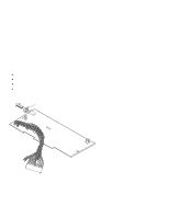
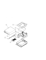
Power Supply Before removing the power supply, perform the following steps: D Remove the stand D Open the system unit D Remove the power supply cover Perform the following steps to remove the power supply: 1. Disconnect all power supply connectors and cables, as shown in Figure 5-22. ac Power Cable Floppy Connector Hard Disk Connector CPU Board Connector Figure 6-22. Removing the Power Supply 2. Remove the screws and lift the power supply from the chassis, as shown in Figure 5-22. 5-32 Field Replaceable Units
-
 1
1 -
2
-
3
-
4
-
5
-
6
-
7
-
8
-
9
-
10
-
11
-
12
-
13
-
14
-
15
-
16
-
17
-
18
-
19
-
20
-
21
-
22
-
23
-
24
-
25
-
26
-
27
-
28
-
29
-
30
-
31
-
32
-
33
-
34
-
35
-
36
-
37
-
38
-
39
-
40
-
41
-
42
-
43
-
44
-
45
-
46
-
47
-
48
-
49
-
50
-
51
-
52
-
53
-
54
-
55
-
56
-
57
-
58
-
59
-
60
-
61
-
62
-
63
-
64
-
65
-
66
-
67
-
68
-
69
-
70
-
71
-
72
-
73
-
74
-
75
-
76
-
77
-
78
-
79
-
80
-
81
-
82
-
83
-
84
-
85
-
86
-
87
-
88
-
89
-
90
-
91
-
92
-
93
-
94
-
95
-
96
-
97
-
98
-
99
-
100
-
101
-
102
-
 103
103 -
 104
104 -
 105
105 -
 106
106 -
 107
107 -
 108
108 -
 109
109 -
 110
110 -
 111
111 -
 112
112 -
 113
113 -
114
-
115
-
116
-
117
-
118
-
119
-
120
-
121
-
122
-
123
-
124
-
125
-
126
-
127
-
128
-
129
-
130
-
131
-
132
-
133
-
134
-
135
-
136
-
137
-
138
-
139
 |
 |

5–32
Field Replaceable Units
Power Supply
Before removing the power supply, perform the following steps:
D
Remove the stand
D
Open the system unit
D
Remove the power supply cover
Perform the following steps to remove the power supply:
1.
Disconnect all power supply connectors and cables, as shown in Figure 5–22.
Floppy
Connector
Hard Disk Connector
CPU Board
Connector
ac Power
Cable
Figure 6–22.
Removing the Power Supply
2.
Remove the screws and lift the power supply from the chassis, as shown in
Figure 5–22.