HP Model 712/100 hp 9000 series 700 model 712 service handbook (a2615-90039) - Page 23
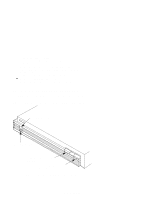
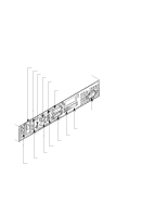
System Unit Rear Panel Connectors
 |
View all HP Model 712/100 manuals
Add to My Manuals
Save this manual to your list of manuals |
Page 23 highlights
System Power Switch Use the Power switch to power the system unit on and off. The Model 712 workstation automatically shuts down HP-UX when powered off. System Power LED The Power Light Emitting Diode (LED) is located on the left side of the front panel. It lights when the system unit power is on and flashes until the OS is booted. A flashing pattern may indicate a problem with the CPU board (see Chapter 4). Floppy Drive Eject Button If a floppy drive is installed in the workstation, an eject button is located on the right side of the front panel. This button removes floppy diskettes from the drive. Floppy Drive Activity LED If a floppy drive is installed in your workstation, an activity LED is located on the right side of the front panel. This LED flashes to indicate use. System Unit Rear Panel Connectors This section describes the following connectors on the system unit's rear panel: D Power cord connector D 802.3 AUI LAN connector D 802.3 TP (Twisted Pair) LAN connector D RS-232C serial input/output connector D monitor connector D SCSI connector D PS2 keyboard and mouse connectors D HP parallel I/O connector D Audio Mic/IN, Head/OUT, and line in connectors D Optional TeleShare board connectors D Optional expansion board connectors NOTICE: To maintain FCC/EMI compliance, verify that all cables are fully seated and properly fastened. 1-4 Product Information
-
 1
1 -
2
-
3
-
4
-
5
-
6
-
7
-
8
-
9
-
10
-
11
-
12
-
13
-
14
-
15
-
16
-
17
-
 18
18 -
 19
19 -
 20
20 -
 21
21 -
 22
22 -
 23
23 -
 24
24 -
 25
25 -
 26
26 -
 27
27 -
 28
28 -
29
-
30
-
31
-
32
-
33
-
34
-
35
-
36
-
37
-
38
-
39
-
40
-
41
-
42
-
43
-
44
-
45
-
46
-
47
-
48
-
49
-
50
-
51
-
52
-
53
-
54
-
55
-
56
-
57
-
58
-
59
-
60
-
61
-
62
-
63
-
64
-
65
-
66
-
67
-
68
-
69
-
70
-
71
-
72
-
73
-
74
-
75
-
76
-
77
-
78
-
79
-
80
-
81
-
82
-
83
-
84
-
85
-
86
-
87
-
88
-
89
-
90
-
91
-
92
-
93
-
94
-
95
-
96
-
97
-
98
-
99
-
100
-
101
-
102
-
103
-
104
-
105
-
106
-
107
-
108
-
109
-
110
-
111
-
112
-
113
-
114
-
115
-
116
-
117
-
118
-
119
-
120
-
121
-
122
-
123
-
124
-
125
-
126
-
127
-
128
-
129
-
130
-
131
-
132
-
133
-
134
-
135
-
136
-
137
-
138
-
139
 |
 |
