HP Pavilion d4000 Upgrading and Servicing Guide - Page 9
Removing a Hard Disk Drive
 |
View all HP Pavilion d4000 manuals
Add to My Manuals
Save this manual to your list of manuals |
Page 9 highlights
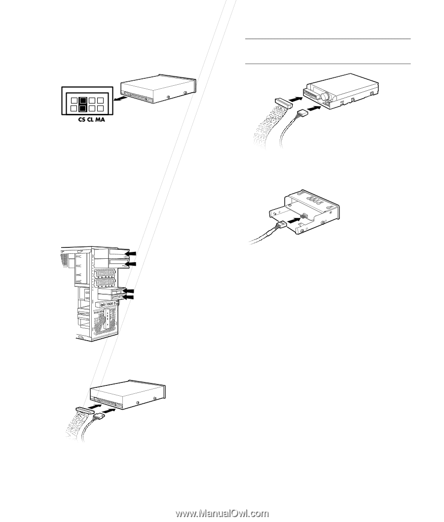
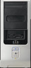
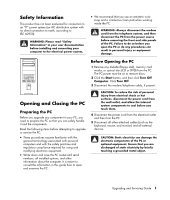
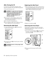
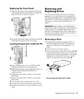
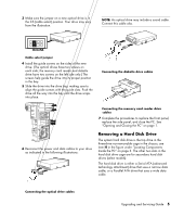
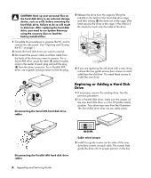
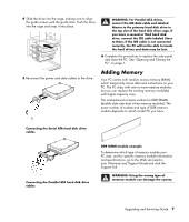
3 Make sure the jumper on a new optical drive is in the CS (cable select) position. Your drive may vary from the illustration. NOTE: An optical drive may include a sound cable. Connect this cable also. Cable select jumper 4 Install the guide screws on the sides of the new drive. (The optical drives have two screws on each side; the memory card reader and diskette drive have two screws on the left side only.) The screws help guide the drive into its proper position in the bay. 5 Slide the drive into the drive bay, making sure to align the guide screws with the guide slots. Push the drive all the way into the bay until the drive snaps into place. Connecting the diskette drive cables 6 Reconnect the power and data cables to your drive as indicated in the following illustrations: Connecting the memory card reader drive cables 7 Complete the procedures to replace the front panel, replace the side panel, and close the PC. See "Opening and Closing the PC" on page 1. Removing a Hard Disk Drive The system hard disk drive is the top drive in the three-drive non-removable cage in the chassis; see item H in the figure under "Locating Components Inside the PC" on page 3. The other two slots in the hard disk drive cage are for secondary hard disk drives (select models). The hard disk drive is either a Serial ATA (advanced technology attachment) drive that uses a narrow data cable, or a Parallel ATA drive that uses a wide data cable. Connecting the optical drive cables Upgrading and Servicing Guide 5
-
 1
1 -
2
-
3
-
 4
4 -
 5
5 -
 6
6 -
 7
7 -
 8
8 -
 9
9 -
 10
10 -
 11
11 -
 12
12 -
 13
13 -
 14
14 -
15
-
16
 |
 |