HP Point of Sale rp5000 Hardware Reference Guide (2nd Edition)
HP Point of Sale rp5000 Manual
 |
View all HP Point of Sale rp5000 manuals
Add to My Manuals
Save this manual to your list of manuals |
HP Point of Sale rp5000 manual content summary:
- HP Point of Sale rp5000 | Hardware Reference Guide (2nd Edition) - Page 1
Hardware Reference Guide HP Point of Sale System rp5000 Document Part Number: 337853-002 June 2005 This guide provides basic information for upgrading this computer model. - HP Point of Sale rp5000 | Hardware Reference Guide (2nd Edition) - Page 2
or loss of life. Ä CAUTION: Text set off in this manner indicates that failure to follow directions could result in damage to equipment or loss of information. Hardware Reference Guide HP Point of Sale System rp5000 First Edition August 2003 Second Edition June 2005 Document Part Number: 337853-002 - HP Point of Sale rp5000 | Hardware Reference Guide (2nd Edition) - Page 3
an Expansion Card 2-10 Removing the HP USB+Power Card 2-12 Installing Additional Drives 2-14 Locating Drive Positions 2-15 Removing an Optical Drive or Diskette Drive 2-16 Installing an Optional Optical Drive 2-19 Upgrading the Hard Drive 2-23 Hardware Reference Guide www.hp.com iii - HP Point of Sale rp5000 | Hardware Reference Guide (2nd Edition) - Page 4
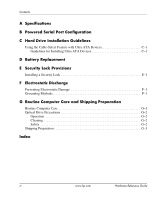
Contents A Specifications B Powered Serial Port Configuration C Hard Drive Installation Guidelines Using the Cable-Select Feature with Ultra ATA Devices C-1 Guidelines for Installing Ultra ATA Devices C-1 D Battery Replacement E Security Lock Provisions Installing a Security Lock E-1 F - HP Point of Sale rp5000 | Hardware Reference Guide (2nd Edition) - Page 5
. For a complete listing of the hardware and software installed in the computer, run the Diagnostics for Windows® utility. Instructions for using this utility are provided in the Troubleshooting Guide on the Documentation CD. HP Point of Sale System rp5000 Hardware Reference Guide www.hp.com 1-1 - HP Point of Sale rp5000 | Hardware Reference Guide (2nd Edition) - Page 6
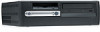
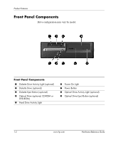
) 2 Diskette Drive (optional) 3 Diskette Eject Button (optional) 4 Optical Drive (optional, CD-ROM or DVD-ROM) 5 Hard Drive Activity Light 6 Power On Light 7 Power Button 8 Optical Drive Activity Light (optional) 9 Optical Drive Eject Button (optional) 1-2 www.hp.com Hardware Reference Guide - HP Point of Sale rp5000 | Hardware Reference Guide (2nd Edition) - Page 7
7 n RJ-45 Network Connector 8 l Parallel Connector 9 c Monitor Connector 4 a PS/2 Keyboard Connector 5 o Universal Serial Bus (USB) : o USB+Power Connector ; k Audio connector 6 m Serial Connector ✎ Arrangement and number of connectors may vary by model. Hardware Reference Guide www.hp.com 1-3 - HP Point of Sale rp5000 | Hardware Reference Guide (2nd Edition) - Page 8
. Launches Windows Help. Locks the computer if you are connected to a network domain, or allows you to switch users if you are not connected to a network domain. Launches the Run dialog box. Launches the Utility Manager. Activates the next Taskbar button. 1-4 www.hp.com Hardware Reference Guide - HP Point of Sale rp5000 | Hardware Reference Guide (2nd Edition) - Page 9
Product Features Removing the Serial Port Cap The powered serial ports have been protected with a plastic cap. Turn off the computer and remove the cap before connecting a powered serial Point of Sale device. Removing the Serial Port Cap Hardware Reference Guide www.hp.com 1-5 - HP Point of Sale rp5000 | Hardware Reference Guide (2nd Edition) - Page 10
Number Location Each computer has a unique serial number and product number that are located on the top cover of the computer. Keep these numbers available for use when contacting customer service for assistance. Serial Number and Product Number Location 1-6 www.hp.com Hardware Reference Guide - HP Point of Sale rp5000 | Hardware Reference Guide (2nd Edition) - Page 11
the power cord from the wall outlet, and allow the internal system components to cool before touching. Å WARNING: To reduce the risk of electrical shock, fire, or damage to the equipment, do not plug telecommunications/telephone connectors into the network interface controller (NIC) receptacles - HP Point of Sale rp5000 | Hardware Reference Guide (2nd Edition) - Page 12
Upgrades Removing the Computer Access Panel and Front Bezel 1. Turn off the computer properly through the operating system, then turn off any external devices. 2. Disconnect the power cord from the power outlet and the computer, and disconnect any external devices. Ä CAUTION: Before removing - HP Point of Sale rp5000 | Hardware Reference Guide (2nd Edition) - Page 13
from the chassis. Removing the Front Bezel To reassemble the computer, reverse the above procedure. ✎ To re-install the front bezel, insert the two bezel bottom tabs, then rotate the front bezel forward to snap the three tabs on the top of the bezel in place. Hardware Reference Guide www.hp.com - HP Point of Sale rp5000 | Hardware Reference Guide (2nd Edition) - Page 14
Upgrades Installing Additional Memory The computer comes with double data rate synchronous dynamic random access memory (DDR1-SDRAM) dual inline memory modules (DIMMs). DIMMs The memory sockets on the system board can be populated with up to two industry-standard DIMMs. These memory module slots - HP Point of Sale rp5000 | Hardware Reference Guide (2nd Edition) - Page 15
system will run at 266 MHz, the highest supported memory speed. Installing DDR1-SDRAM DIMMs Ä CAUTION: The memory module sockets have gold metal contacts. When upgrading the memory, it is important to use memory Electrostatic Discharge" for more information. Hardware Reference Guide www.hp.com 2-5 - HP Point of Sale rp5000 | Hardware Reference Guide (2nd Edition) - Page 16
properly through the operating system, then turn off any external devices. 2. Disconnect the power cord from the power outlet and disconnect any external devices. 3. Remove the computer access panel and front bezel (see "Removing the Computer Access Panel and Front Bezel" in this chapter). Ä CAUTION - HP Point of Sale rp5000 | Hardware Reference Guide (2nd Edition) - Page 17
can be installed in only one way. Match the notch on the module with the tab on the memory socket. 7. Push the module down into the socket, ensuring that the module is fully inserted and properly seated. Make sure the latches are in the closed position 3. Hardware Reference Guide www.hp.com 2-7 - HP Point of Sale rp5000 | Hardware Reference Guide (2nd Edition) - Page 18
drive bay. 10. Replace the front bezel and computer access panel. The computer automatically recognizes the additional memory the next time you power on the computer. Removing the Expansion Card Cage To remove the expansion card cage: 1. Turn off the computer properly through the operating system - HP Point of Sale rp5000 | Hardware Reference Guide (2nd Edition) - Page 19
up to remove it from the chassis. Removing the Expansion Card Cage To replace the expansion card cage, reverse the above procedure. ✎ Ensure that the riser card seats properly into the PCI connector on the system board when reinstalling the expansion card cage. Hardware Reference Guide www.hp.com - HP Point of Sale rp5000 | Hardware Reference Guide (2nd Edition) - Page 20
Access Panel and Front Bezel" in this chapter). 4. Remove the expansion card cage and identify the slot into which you want to insert the expansion card (see "Removing the Expansion Card Cage" in this chapter). 5. Release the slot cover retention latch 1 that secures the PCI slot covers by rotating - HP Point of Sale rp5000 | Hardware Reference Guide (2nd Edition) - Page 21
card slot. 9. Replace the expansion card cage. Ä CAUTION: If you remove an expansion card, you must replace it with a new card or cover the open slot (for example, with a metal slot cover) for proper air circulation to cool internal components during operation. Hardware Reference Guide www.hp.com - HP Point of Sale rp5000 | Hardware Reference Guide (2nd Edition) - Page 22
computer access panel (see "Removing the Computer Access Panel and Front Bezel" in this chapter). 4. Locate the USB+Power card on the system board. 5. Lift up the slot cover retention latch that secures the card. Releasing the Slot Cover Retention Latch 2-12 www.hp.com Hardware Reference Guide - HP Point of Sale rp5000 | Hardware Reference Guide (2nd Edition) - Page 23
card straight up, then pull it in toward the center of the chassis to maneuver it around the chassis frame. Be sure not to scrape the card against other components. Removing the USB+Power Card To replace the USB+Power card, reverse the above procedure. Hardware Reference Guide www.hp.com 2-13 - HP Point of Sale rp5000 | Hardware Reference Guide (2nd Edition) - Page 24
cage and lock in place. HP has provided extra guide screws (four 6-32 standard screws and four M3 metric screws), installed in the front of the chassis, behind the bezel. The hard drive uses 6-32 standard screws. All other drives use M3 metric screws. The HP-supplied metric screws are black and the - HP Point of Sale rp5000 | Hardware Reference Guide (2nd Edition) - Page 25
Upgrades Desktop Drive Positions 1 3.5-inch drive bay (1.44-MB diskette drive shown)* 2 5.25-inch drive bay for optional drives* 3 3.5-inch, internal, standard hard drive bay *If the computer has a 1.44-MB diskette drive or 5.25-inch optical drive installed, it will be configured with a drive bezel - HP Point of Sale rp5000 | Hardware Reference Guide (2nd Edition) - Page 26
front bezel (see "Removing the Computer Access Panel and Front Bezel" in this chapter). 4. Raise the Easy Access drive bay to the upright position. 5. Disconnect the signal and drive power cables. 6. Return the Easy Access drive bay to the down position. 2-16 www.hp.com Hardware Reference Guide - HP Point of Sale rp5000 | Hardware Reference Guide (2nd Edition) - Page 27
Upgrades 7. Push the drive release latch 1 toward the rear of the chassis and hold. 8. Slide the drive 2 toward the front of the drive cage, then lift the drive out of the computer. Removing the Optical Drive or Diskette Drive To replace the drive, reverse the removal procedures. ✎ When replacing - HP Point of Sale rp5000 | Hardware Reference Guide (2nd Edition) - Page 28
Hardware Upgrades To install the 5.25-inch bezel blank, align the bezel blank as shown in the following illustration and snap it into place. Installing a 5.25-inch Bezel Blank 2-18 www.hp.com Hardware Reference Guide - HP Point of Sale rp5000 | Hardware Reference Guide (2nd Edition) - Page 29
, you cannot install a secondary hard drive. There are not enough power supply connectors to support this configuration. Doing so could result in damage to the computer. To install an optional optical drive: 1. Turn off the computer properly through the operating system, then turn off any external - HP Point of Sale rp5000 | Hardware Reference Guide (2nd Edition) - Page 30
Hardware Upgrades ✎ When replacing the drive, transfer the four screws from the old drive to the new one. The screws take the place of drive rails. Installing Guide Screws in the Optical Drive 2-20 www.hp.com Hardware Reference Guide - HP Point of Sale rp5000 | Hardware Reference Guide (2nd Edition) - Page 31
Hardware Upgrades 6. Position the guide screws on the drive into the J-slots in the drive bay 1. Then, slide the drive toward the rear of the computer 2. Installing the Optical Drive ✎ The drive release latch automatically locks in place when installing a drive. Hardware Reference Guide www.hp. - HP Point of Sale rp5000 | Hardware Reference Guide (2nd Edition) - Page 32
. Be sure not to pinch the cables in the chassis when lowering the Easy Access drive bay. 10. Replace the front bezel and computer access panel. The system automatically recognizes the drive and reconfigures the computer. Ä CAUTION: When servicing the computer, ensure that cables are placed in their - HP Point of Sale rp5000 | Hardware Reference Guide (2nd Edition) - Page 33
. To remove and replace the hard drive: 1. Turn off the computer properly through the operating system, then turn off any external devices. 2. Disconnect the power cord from the power outlet and disconnect any external devices. 3. Remove the computer access panel and front bezel (see "Removing the - HP Point of Sale rp5000 | Hardware Reference Guide (2nd Edition) - Page 34
3. Removing the Hard Drive To replace the hard drive, reverse the above procedure. ✎ When replacing the hard drive, transfer the four screws from the old drive to the new one. The screws take the place of drive rails. You will need a Torx T-15 screwdriver to remove and re-install the guide screws - HP Point of Sale rp5000 | Hardware Reference Guide (2nd Edition) - Page 35
a bezel blank. If you are installing a 3.5-inch device other than a diskette drive or hard drive, you must install the 3.5-inch device bezel. Contact an authorized HP reseller or service provider to order the appropriate bezel when reconfiguring the computer. Hardware Reference Guide www.hp.com - HP Point of Sale rp5000 | Hardware Reference Guide (2nd Edition) - Page 36
2. Guide Screw Locations To install a drive into the bay: 1. Turn off the computer properly through the operating system, then turn off any external devices. 2. Disconnect the power cord from the power outlet and disconnect any external devices. 3. Remove the computer access panel and front bezel - HP Point of Sale rp5000 | Hardware Reference Guide (2nd Edition) - Page 37
Hardware Upgrades 4. Remove the diskette drive bezel by pushing the tab inward 1 and pulling the diskette drive bezel 2 away from the front bezel. ✎ The type of bezel will vary depending on the computer configuration. Removing the Diskette Drive Bezel Hardware Reference Guide www.hp.com 2-27 - HP Point of Sale rp5000 | Hardware Reference Guide (2nd Edition) - Page 38
not enough power supply connectors to support this configuration.Doing so could result in damage to the computer. See "Removing an Optical Drive or Diskette Drive" for instructions on removing an optical drive and installing a bezel blank. ✎ If replacing a diskette drive, the guide screws (front and - HP Point of Sale rp5000 | Hardware Reference Guide (2nd Edition) - Page 39
diskette drive or hard drive, you must install the 3.5-inch device bezel. Contact an authorized HP reseller or service provider to order the appropriate bezel when reconfiguring the computer. Replacing the 3.5-inch Bezel 7. Connect the power and data cables. 8. Replace the front bezel and computer - HP Point of Sale rp5000 | Hardware Reference Guide (2nd Edition) - Page 40
- HP Point of Sale rp5000 | Hardware Reference Guide (2nd Edition) - Page 41
A Specifications HP Point of Sale System rp5000 Desktop Dimensions Height 3.95 inches 10.3 cm Width 13.3 inches 33.78 cm Depth (depth will increase of change is 10° C/Hr. The upper limit may be limited by the type and number of options installed. Hardware Reference Guide www.hp.com A-1 - HP Point of Sale rp5000 | Hardware Reference Guide (2nd Edition) - Page 42
Specifications HP Point of Sale System rp5000 Power Supply 115 V 230 V Operating Voltage Range 90-132 VAC 180-264 VAC Rated Voltage Range 100-127 VAC 200-240 VAC Rated Line Frequency 50-60 Hz 50-60 Hz Power Output 185 W 185 W Rated Input Current (maximum) 5 A @ 100 VAC 2.5 A @ 200 - HP Point of Sale rp5000 | Hardware Reference Guide (2nd Edition) - Page 43
the power outlet and disconnect any external devices. 3. Remove the computer access panel and front bezel (see Chapter 2, "Removing the Computer Access Panel and Front Bezel"). 4. Raise the Easy Access drive bay to the upright position to access the system board. Hardware Reference Guide www.hp - HP Point of Sale rp5000 | Hardware Reference Guide (2nd Edition) - Page 44
Replace the USB+Power card, if you removed it 9. Return the Easy Access drive bay to the down position. 10. Replace the front bezel and computer access panel. 11. If the serial ports are configured in powered mode, connect the powered Point of Sale device. B-2 www.hp.com Hardware Reference Guide - HP Point of Sale rp5000 | Hardware Reference Guide (2nd Edition) - Page 45
Powered Serial Port Configuration The serial port jumpers are located as shown in the illustration below: Serial Port Jumper Locations Hardware Reference Guide www.hp.com B-3 - HP Point of Sale rp5000 | Hardware Reference Guide (2nd Edition) - Page 46
- HP Point of Sale rp5000 | Hardware Reference Guide (2nd Edition) - Page 47
this appendix for an example of an Ultra ATA cable. HP hard drives ship with jumpers preset to cable-select mode; therefore, no jumper setting changes on the existing or optional drives are required. If you purchase a third-party hard drive, refer to the documentation included with the kit to ensure - HP Point of Sale rp5000 | Hardware Reference Guide (2nd Edition) - Page 48
screws to ensure that the drive lines up correctly in the drive cage. HP has provided extra guide screws installed in the front of the computer chassis behind the front bezel. Some options use M3 metric hardware. HP-supplied metric screws are black. HP-supplied standard screws are silver. ■ If only - HP Point of Sale rp5000 | Hardware Reference Guide (2nd Edition) - Page 49
or water. ■ Replace the battery only with the HP spare designated for this product. Ä CAUTION: Before replacing the battery, it is important to back up the computer CMOS settings. When the battery is removed or replaced, the CMOS settings will be cleared. Refer to the Troubleshooting Guide on the - HP Point of Sale rp5000 | Hardware Reference Guide (2nd Edition) - Page 50
Panel and Front Bezel"). ✎ It may be necessary to remove an expansion card to gain access to the battery. 2. Locate the battery and battery holder on the system board. 3. Depending on the type of battery holder on the system board, complete the following instructions to replace the battery. Type - HP Point of Sale rp5000 | Hardware Reference Guide (2nd Edition) - Page 51
Battery Replacement Type 2 a. To release the battery from its holder, squeeze the metal clamp that extends above one edge of the battery. b. When the battery pops up, lift it out. Removing a Coin Cell Battery (Type 2) Hardware Reference Guide www.hp.com D-3 - HP Point of Sale rp5000 | Hardware Reference Guide (2nd Edition) - Page 52
this procedure. 4. Replace the computer access panel. 5. Plug in the computer and turn on power to the computer. 6. Reset the date and time, your passwords, and any special system setups, using Computer Setup. Refer to the Computer Setup (F10) Utility Guide on the Documentation CD. D-4 www.hp.com - HP Point of Sale rp5000 | Hardware Reference Guide (2nd Edition) - Page 53
E Security Lock Provisions Installing a Security Lock The security locks displayed below and on the following page can be used to secure the computer. Installing a Cable Lock Hardware Reference Guide www.hp.com E-1 - HP Point of Sale rp5000 | Hardware Reference Guide (2nd Edition) - Page 54
Security Lock Provisions I Installing a Padlock E-2 www.hp.com Hardware Reference Guide - HP Point of Sale rp5000 | Hardware Reference Guide (2nd Edition) - Page 55
finger or other conductor may damage system boards or other static-sensitive devices. . ■ Place parts on a grounded surface before removing them from their containers. ■ Avoid touching pins a ground cord to a grounded workstation or computer chassis. Wrist straps are flexible straps with a minimum of - HP Point of Sale rp5000 | Hardware Reference Guide (2nd Edition) - Page 56
work mat. If you do not have any of the suggested equipment for proper grounding, contact an HP authorized dealer, reseller, or service provider. ✎ For more information on static electricity, contact an HP authorized dealer, reseller, or service provider. F-2 www.hp.com Hardware Reference Guide - HP Point of Sale rp5000 | Hardware Reference Guide (2nd Edition) - Page 57
about the recommended temperature and humidity ranges for the computer, refer to Appendix A, "Specifications" in this guide. ■ Keep liquids away from the computer and keyboard. ■ Never cover the ventilation slots on the monitor with any type of material. ■ Turn off the computer before you - HP Point of Sale rp5000 | Hardware Reference Guide (2nd Edition) - Page 58
. ■ Avoid using any type of solvent, such as alcohol or benzene, which may damage the finish. Safety If any object or liquid falls into the drive, immediately unplug the computer and have it checked by an authorized HP service provider. G-2 www.hp.com Hardware Reference Guide - HP Point of Sale rp5000 | Hardware Reference Guide (2nd Edition) - Page 59
magnetic impulses while stored or in transit. ✎ The hard drive locks automatically when the system power is turned off. 2. Remove and store any program diskettes from the diskette drives. 3. Insert a blank diskette into the diskette drive to protect the drive while in transit. Do not use a diskette - HP Point of Sale rp5000 | Hardware Reference Guide (2nd Edition) - Page 60
- HP Point of Sale rp5000 | Hardware Reference Guide (2nd Edition) - Page 61
card, installing 2-10 expansion slot cover 2-10 F front bezel, removing 2-3 front panel components 1-2 G guidelines battery replacement D-1 computer care G-1 DDR-SDRAM DIMMs 2-4 drive installation 2-14 optical drive G-2 shipping preparation G-3 Ultra ATA installation C-1 www.hp.com Index-1 - HP Point of Sale rp5000 | Hardware Reference Guide (2nd Edition) - Page 62
1-3 light 1-2 powered serial ports See serial ports R rear panel components 1-3 removing bezel blank 2-27 coin cell battery (type 1) D-2 coin cell battery (type 2) D-3 computer access panel 2-2 diskette drive 2-16 expansion card cage 2-8, 2-9 expansion slot cover 2-10 front bezel 2-3 hard drive 2-24 - HP Point of Sale rp5000 | Hardware Reference Guide (2nd Edition) - Page 63
ports B-1 jumper location B-3 powered B-1 Index standard B-1 shipping preparation, guidelines G-3 socket locations, DIMM 2-5 U Ultra ATA cable-select feature C-1 installation guidelines C-1 USB+Power card 2-12 removing 2-12 W Windows Logo key 1-4 Hardware Reference Guide www.hp.com Index-3
-
 1
1 -
 2
2 -
 3
3 -
 4
4 -
 5
5 -
 6
6 -
 7
7 -
8
-
9
-
10
-
11
-
12
-
13
-
14
-
15
-
16
-
17
-
18
-
19
-
20
-
21
-
22
-
23
-
24
-
25
-
26
-
27
-
28
-
29
-
30
-
31
-
32
-
33
-
34
-
35
-
36
-
37
-
38
-
39
-
40
-
41
-
42
-
43
-
44
-
45
-
46
-
47
-
48
-
49
-
50
-
51
-
52
-
53
-
54
-
55
-
56
-
57
-
58
-
59
-
60
-
61
-
62
-
63
 |
 |

Hardware Reference Guide
HP Point of Sale System rp5000
Document Part Number: 337853-002
June 2005
This guide provides basic information for upgrading this computer
model.