HP Tx1220us HP Pavilion tx1000 Entertainment PC - Maintenance and Service Guid - Page 58
The display connector cover is included in the Plastics Kit, spare part number
 |
View all HP Tx1220us manuals
Add to My Manuals
Save this manual to your list of manuals |
Page 58 highlights
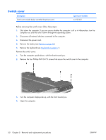
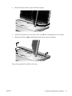
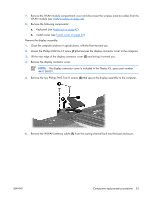
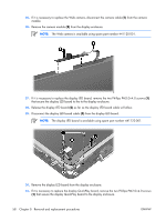
7. Remove the WLAN module compartment cover and disconnect the wireless antenna cables from the WLAN module (see WLAN module on page 44). 8. Remove the following components:. a. Keyboard (see Keyboard on page 47) b. Switch cover (see Switch cover on page 50) Remove the display assembly: 1. Close the computer and turn it upside down, with the front toward you. 2. Loosen the Phillips PM2.0×4.0 screw (1) that secures the display connector cover to the computer. 3. Lift the rear edge of the display connector cover (2) and swing it toward you. 4. Remove the display connector cover. NOTE: The display connector cover is included in the Plastics Kit, spare part number 441138-001. 5. Remove the two Phillips PM2.5×6.0 screws (3) that secure the display assembly to the computer. 6. Remove the WWAN antenna cable (1) from the routing channel built into the base enclosure. ENWW Component replacement procedures 53
-
 1
1 -
2
-
3
-
4
-
5
-
6
-
7
-
8
-
9
-
10
-
11
-
12
-
13
-
14
-
15
-
16
-
17
-
18
-
19
-
20
-
21
-
22
-
23
-
24
-
25
-
26
-
27
-
28
-
29
-
30
-
31
-
32
-
33
-
34
-
35
-
36
-
37
-
38
-
39
-
40
-
41
-
42
-
43
-
44
-
45
-
46
-
47
-
48
-
49
-
50
-
51
-
52
-
 53
53 -
 54
54 -
 55
55 -
 56
56 -
 57
57 -
 58
58 -
 59
59 -
 60
60 -
 61
61 -
 62
62 -
 63
63 -
64
-
65
-
66
-
67
-
68
-
69
-
70
-
71
-
72
-
73
-
74
-
75
-
76
-
77
-
78
-
79
-
80
-
81
-
82
-
83
-
84
-
85
-
86
-
87
-
88
-
89
-
90
-
91
-
92
-
93
-
94
-
95
-
96
-
97
-
98
-
99
-
100
-
101
-
102
-
103
-
104
-
105
-
106
-
107
-
108
-
109
-
110
-
111
-
112
-
113
-
114
-
115
-
116
-
117
-
118
-
119
-
120
-
121
-
122
-
123
-
124
-
125
-
126
-
127
-
128
-
129
-
130
-
131
 |
 |
