HP Tx1220us HP Pavilion tx1000 Entertainment PC - Maintenance and Service Guid - Page 76
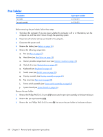
Fan/heat sink assembly, Reverse this procedure to install the WWAN external antenna board.
 |
View all HP Tx1220us manuals
Add to My Manuals
Save this manual to your list of manuals |
Page 76 highlights
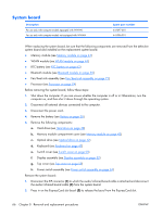
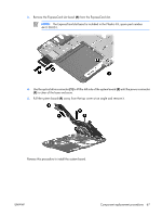
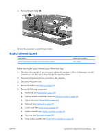
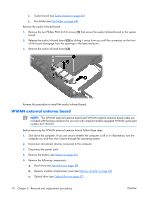
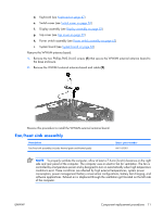
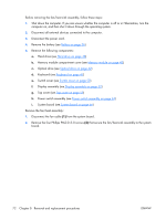
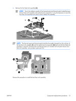
d. Keyboard (see Keyboard on page 47) e. Switch cover (see Switch cover on page 50) f. Display assembly (see Display assembly on page 52) g. Top cover (see Top cover on page 59) h. Power switch assembly (see Power switch assembly on page 63) i. System board (see System board on page 66) Remove the WWAN antenna board: 1. Remove the two Phillips PM2.0×4.0 screws (1) that secure the WWAN external antenna board to the base enclosure. 2. Remove the WWAN external antenna board and cable (2). Reverse this procedure to install the WWAN external antenna board. Fan/heat sink assembly Description Fan/heat sink assembly (includes thermal paste and thermal pads) Spare part number 441143-001 NOTE: To properly ventilate the computer, allow at least a 7.6-cm (3-inch) clearance on the right side and rear panel of the computer. The computer uses an electric fan for ventilation. The fan is controlled by a temperature sensor and is designed to turn on automatically when high temperature conditions exist. These conditions are affected by high external temperatures, system power consumption, power management/battery conservation configurations, battery fast charging, and software applications. Exhaust air is displaced through the ventilation grill located on the left side of the computer. ENWW Component replacement procedures 71
-
 1
1 -
2
-
3
-
4
-
5
-
6
-
7
-
8
-
9
-
10
-
11
-
12
-
13
-
14
-
15
-
16
-
17
-
18
-
19
-
20
-
21
-
22
-
23
-
24
-
25
-
26
-
27
-
28
-
29
-
30
-
31
-
32
-
33
-
34
-
35
-
36
-
37
-
38
-
39
-
40
-
41
-
42
-
43
-
44
-
45
-
46
-
47
-
48
-
49
-
50
-
51
-
52
-
53
-
54
-
55
-
56
-
57
-
58
-
59
-
60
-
61
-
62
-
63
-
64
-
65
-
66
-
67
-
68
-
69
-
70
-
 71
71 -
 72
72 -
 73
73 -
 74
74 -
 75
75 -
 76
76 -
 77
77 -
 78
78 -
 79
79 -
 80
80 -
 81
81 -
82
-
83
-
84
-
85
-
86
-
87
-
88
-
89
-
90
-
91
-
92
-
93
-
94
-
95
-
96
-
97
-
98
-
99
-
100
-
101
-
102
-
103
-
104
-
105
-
106
-
107
-
108
-
109
-
110
-
111
-
112
-
113
-
114
-
115
-
116
-
117
-
118
-
119
-
120
-
121
-
122
-
123
-
124
-
125
-
126
-
127
-
128
-
129
-
130
-
131
 |
 |
