HP Tx1220us HP Pavilion tx1000 Entertainment PC - Maintenance and Service Guid - Page 61
for use only with computer models equipped with a Web camera, but
 |
View all HP Tx1220us manuals
Add to My Manuals
Save this manual to your list of manuals |
Page 61 highlights
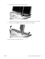
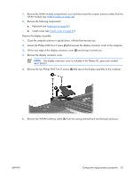
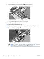
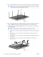
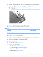
15. Remove the eight Phillips PM2.0×7.0 screws that secure the display bezel to the display assembly. NOTE: All screws used to secure display assembly internal subcomponents are available in the Display Screw Kit, spare part number 441124-001. 16. Flex the inside edges of the right side (1) of the display bezel and the inside edges of the top and bottom sides (2) of the display bezel until the bezel disengages from the display assembly. 17. Swing the right side of the display bezel (3) to the left until it rests upside down on the left side of the display assembly. NOTE: Display bezels are available using the following spare part numbers: ● 441117-001 - for use only with computer models equipped with a Web camera and fingerprint reader ● 441116-001 - for use only with computer models equipped with a Web camera, but not fingerprint reader ● 441118-001 - for use only with computer models equipped with a fingerprint reader, but not a Web camera ● 441115-001 - for use only with computer models not equipped with a Web camera or fingerprint reader 56 Chapter 5 Removal and replacement procedures ENWW
-
 1
1 -
2
-
3
-
4
-
5
-
6
-
7
-
8
-
9
-
10
-
11
-
12
-
13
-
14
-
15
-
16
-
17
-
18
-
19
-
20
-
21
-
22
-
23
-
24
-
25
-
26
-
27
-
28
-
29
-
30
-
31
-
32
-
33
-
34
-
35
-
36
-
37
-
38
-
39
-
40
-
41
-
42
-
43
-
44
-
45
-
46
-
47
-
48
-
49
-
50
-
51
-
52
-
53
-
54
-
55
-
 56
56 -
 57
57 -
 58
58 -
 59
59 -
 60
60 -
 61
61 -
 62
62 -
 63
63 -
 64
64 -
 65
65 -
 66
66 -
67
-
68
-
69
-
70
-
71
-
72
-
73
-
74
-
75
-
76
-
77
-
78
-
79
-
80
-
81
-
82
-
83
-
84
-
85
-
86
-
87
-
88
-
89
-
90
-
91
-
92
-
93
-
94
-
95
-
96
-
97
-
98
-
99
-
100
-
101
-
102
-
103
-
104
-
105
-
106
-
107
-
108
-
109
-
110
-
111
-
112
-
113
-
114
-
115
-
116
-
117
-
118
-
119
-
120
-
121
-
122
-
123
-
124
-
125
-
126
-
127
-
128
-
129
-
130
-
131
 |
 |
