HP ap5000 Hardware Reference Guide HP ap5000 All-In-One Point of Sale System
HP ap5000 - All-in-One Point of Sale System Manual
 |
View all HP ap5000 manuals
Add to My Manuals
Save this manual to your list of manuals |
HP ap5000 manual content summary:
- HP ap5000 | Hardware Reference Guide HP ap5000 All-In-One Point of Sale System - Page 1
Hardware Reference Guide HP ap5000 All-In-One Point of Sale System - HP ap5000 | Hardware Reference Guide HP ap5000 All-In-One Point of Sale System - Page 2
by copyright. No part of this document may be photocopied, reproduced, or translated to another language without the prior written consent of Hewlett-Packard Company. Hardware Reference Guide HP ap5000 All-In-One Point of Sale System First Edition (January 2010) Document Part Number: 592989-001 - HP ap5000 | Hardware Reference Guide HP ap5000 All-In-One Point of Sale System - Page 3
About This Book This guide provides basic information for upgrading this computer model. WARNING! Text set off in this manner indicates that failure to follow directions could result in bodily harm or loss of life. CAUTION: Text set - HP ap5000 | Hardware Reference Guide HP ap5000 All-In-One Point of Sale System - Page 4
iv About This Book ENWW - HP ap5000 | Hardware Reference Guide HP ap5000 All-In-One Point of Sale System - Page 5
Replacing the Power Supply 19 Installing Additional Memory ...22 DIMMs ...22 DDR2-SDRAM DIMMs ...22 Installing DIMMs ...22 3 Configuring the Software ...27 Calibrating the Touch Screen ...27 Configuring the MSR and VFD Customer Display 27 Configuring the COM Port for the VFD Customer Display 27 - HP ap5000 | Hardware Reference Guide HP ap5000 All-In-One Point of Sale System - Page 6
Appendix A Electrostatic Discharge ...29 Preventing Electrostatic Damage ...29 Grounding Methods ...29 Appendix B Computer Operating Guidelines, Routine Care and Shipping Preparation 30 Computer Operating Guidelines and Routine Care 30 Shipping Preparation ...30 Index ...32 vi ENWW - HP ap5000 | Hardware Reference Guide HP ap5000 All-In-One Point of Sale System - Page 7
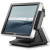
HP ap5000 All-In-One Point of Sale System features include: ● Water-resistant touch screen so wet fingers are not be a problem. You can use a stylus, finger tip, finger nail, or credit card edge on the touch screen. ● Two-line customer facing vacuum fluorescent display (VFD). ● Three-track magnetic - HP ap5000 | Hardware Reference Guide HP ap5000 All-In-One Point of Sale System - Page 8
Components Figure 1-1 System Components 1 Touch Screen 2 Power LED 3 Magnetic Stripe Reader (MSR) 4 VFD Customer Display 5 Drive Cover 6 Adjustable VFD Hinge 7 Adjustable Touch Screen Hinge 8 Print Advertisement Panel 9 Base and Power Supply Housing 10 Bottom I/O Cover 11 Power Button 12 Side - HP ap5000 | Hardware Reference Guide HP ap5000 All-In-One Point of Sale System - Page 9
Components Figure 1-2 Bottom I/O Panel Connectors 1 Kensington Lock Slot 2 Serial Connector (COM2, 5V) 3 Parallel Connector 4 RJ-45 Network Connector 5 24V USB+POWER Connector 6 Power Button 7 PS/2 Keyboard Connector 8 Serial Connector (COM1, 5V) 9 Serial Connector (COM3, 12V) 10 VGA Connector 11 - HP ap5000 | Hardware Reference Guide HP ap5000 All-In-One Point of Sale System - Page 10
Side Panel Components Figure 1-3 Side Connectors 1 Primary Hard Drive 2 Secondary Hard Drive Bay 3 Audio Line-Out Connector (green) 4 Microphone Connector (pink) 5 Universal Serial Bus (USB) Connector 4 Chapter 1 Product Features ENWW - HP ap5000 | Hardware Reference Guide HP ap5000 All-In-One Point of Sale System - Page 11
. It describes proper workstation, setup, posture, and health and work habits for computer users, and provides important electrical and mechanical safety information. This guide is located on the Web at http://www.hp.com/ergo. CAUTION: Static electricity can damage the electrical components of the - HP ap5000 | Hardware Reference Guide HP ap5000 All-In-One Point of Sale System - Page 12
Removing the Bottom I/O Cover To remove the bottom I/O cover, press downward on the two tabs at the top of the cover (1) and rotate the cover off (2). Figure 2-1 Removing the Bottom I/O Cover Replacing the Bottom I/O Cover To replace the bottom I/O cover, insert the bottom of the cover (1) and - HP ap5000 | Hardware Reference Guide HP ap5000 All-In-One Point of Sale System - Page 13
Removing the Side I/O Cover To remove the side I/O cover, pull out on the center of the cover (1) and rotate the cover off (2). Figure 2-3 Removing the Side I/O Cover Replacing the Side I/O Cover To replace the side I/O cover, slide the hook on the side I/O cover into the slot on the larger drive - HP ap5000 | Hardware Reference Guide HP ap5000 All-In-One Point of Sale System - Page 14
Cover To remove the drive cover, loosen the screw that holds the cover in place (1), rotate the cover back (2), and pull the cover off the display head (3). NOTE: The drive cover screw is captive, therefore it does not disengage from the drive cover when loosened. Figure 2-5 Removing the Drive Cover - HP ap5000 | Hardware Reference Guide HP ap5000 All-In-One Point of Sale System - Page 15
Routing Cables When connecting peripherals to the bottom I/O panel, route the peripheral cables through the bottom of the base and out the center hole at the top of the base before connecting. Figure 2-7 Routing Cables ENWW Routing Cables 9 - HP ap5000 | Hardware Reference Guide HP ap5000 All-In-One Point of Sale System - Page 16
Adjusting the Tilt The main touch screen display has a 90 degree tilt range. The VFD customer display has an 80 degree tilt range. Figure 2-8 Adjusting the Touch Screen Display Tilt Figure 2-9 Adjusting the VFD Customer Display Tilt 10 Chapter 2 Hardware Upgrades ENWW - HP ap5000 | Hardware Reference Guide HP ap5000 All-In-One Point of Sale System - Page 17
2-10 Removing the Print Advertisement Panel Cover 2. Insert a print advertisement behind the panel cover. NOTE: A print advertisement panel template is available on the system's hard drive. In Windows XP or Windows Embedded POSReady 2009, select Start > All Programs > HP Point of Sale Information - HP ap5000 | Hardware Reference Guide HP ap5000 All-In-One Point of Sale System - Page 18
I/O cover (see Removing the Bottom I/O Cover on page 6). 2. Install the cable lock into the lock slot on the bottom I/O panel. Figure 2-12 Installing an HP/Kensington MicroSaver Security Cable Lock 3. Replace the bottom I/O cover (see Replacing the Bottom I/O Cover on page 6). 12 Chapter 2 Hardware - HP ap5000 | Hardware Reference Guide HP ap5000 All-In-One Point of Sale System - Page 19
You must disconnect the power cord to avoid damage to the internal components of the computer. 3. Remove the bottom I/O cover (see Removing the Bottom I/O Cover on page 6). 4. Unplug the VFD customer display's serial cable from the I/O panel. 5. Remove the plastic VFD hinge bracket cover by pulling - HP ap5000 | Hardware Reference Guide HP ap5000 All-In-One Point of Sale System - Page 20
the two screws below the display screen (1) and slide the display off the system (2). Figure 2-14 Removing the VFD Customer Display 7. Route the serial cable of the new display through the center hole in the hinge area and connect the cable to the same COM port on the I/O panel that was used for the - HP ap5000 | Hardware Reference Guide HP ap5000 All-In-One Point of Sale System - Page 21
that secure it in place (2). Figure 2-16 Replacing the VFD Customer Display 10. Attach the hinge bracket cover by placing the upper sides of Reconnect the power cord and press the power button. 13. Configure the new customer display (refer to Configuring the MSR and VFD Customer Display on page - HP ap5000 | Hardware Reference Guide HP ap5000 All-In-One Point of Sale System - Page 22
old hard drive so that you can transfer the data to the new hard drive. 1. Turn off the computer properly through the operating system, then turn off any external devices. 2. Disconnect the power cord from the power outlet. CAUTION: Regardless of the power-on state, voltage is always present on the - HP ap5000 | Hardware Reference Guide HP ap5000 All-In-One Point of Sale System - Page 23
drive from the plastic carrier, pull up on the two ends on one side of the carrier (1) and rotate the drive out of the To insert the new drive in the carrier, hold the drive at a slight angle and place one side of the hard drive in the carrier (1), then press the other side straight down into the - HP ap5000 | Hardware Reference Guide HP ap5000 All-In-One Point of Sale System - Page 24
has the connector going in first. Figure 2-21 Replacing the Hard Drive 8. Replace the drive cover (see Replacing the Drive Cover on page 8). 9. Reconnect the power cord and press the power button. 18 Chapter 2 Hardware Upgrades ENWW - HP ap5000 | Hardware Reference Guide HP ap5000 All-In-One Point of Sale System - Page 25
soft, clean, dry cloth to avoid scratching the touch screen. 4. Remove the bottom I/O cover (see Removing the Bottom I/O Cover on page 6). 5. Unplug the power cord from the connector on the I/O panel. 6. Loosen the thumbscrew that secures the power supply bracket to the bottom of the unit (1), then - HP ap5000 | Hardware Reference Guide HP ap5000 All-In-One Point of Sale System - Page 26
. Figure 2-23 Removing the Power Supply 8. Connect the external power cord to the power supply. 9. Route the circular end of the power cord through the hole at the top of the base and connect the power cord to the power connector on the bottom I/O panel. 10. Place the power supply into the base so - HP ap5000 | Hardware Reference Guide HP ap5000 All-In-One Point of Sale System - Page 27
thumbscrew (2). Figure 2-25 Replacing the Power Supply Bracket 12. Replace the bottom I/O cover (see Replacing the Bottom I/O Cover on page 6). 13. Turn the unit over and onto its base. 14. Plug the power cord into an electrical outlet and press the power button. ENWW Removing and Replacing the - HP ap5000 | Hardware Reference Guide HP ap5000 All-In-One Point of Sale System - Page 28
not supported NOTE: The system will not start if you install unsupported DIMMs. Installing DIMMs CAUTION: You must disconnect the power cord and wait approximately 30 seconds for the power to drain before adding or removing memory modules. Regardless of the power-on state, voltage is always supplied - HP ap5000 | Hardware Reference Guide HP ap5000 All-In-One Point of Sale System - Page 29
are located on the system board behind the touch screen. You must remove the drive cover, remove the MSR, and disassemble the touch screen display head to access the memory. 1. Turn off the computer properly through the operating system, then turn off any external devices. 2. Disconnect the power - HP ap5000 | Hardware Reference Guide HP ap5000 All-In-One Point of Sale System - Page 30
the Display Head Screws 10. Lift the bottom side of the display head housing (where the two screws were removed) off the touch screen (1), then lift the top side off the housing off the touch screen (2). Figure 2-28 Removing the Display Head 11. Locate the memory module sockets on the system board - HP ap5000 | Hardware Reference Guide HP ap5000 All-In-One Point of Sale System - Page 31
12 and 13 to install any additional modules. 15. After installing the memory module(s), place the top of the display head housing onto the display head (1), then set the bottom of the display head housing onto the display head (2). Figure 2-30 Replacing the Display Head ENWW Installing Additional - HP ap5000 | Hardware Reference Guide HP ap5000 All-In-One Point of Sale System - Page 32
Display Head 17. Connect the MSR cable (1), place the MSR onto the side of the display head (2), and replace the two screws that hold the MSR in place (3). Figure 2-32 Replacing the MSR 18. Turn the unit over and onto its base. 19. Plug the power cord and all peripherals into the bottom I/O panel - HP ap5000 | Hardware Reference Guide HP ap5000 All-In-One Point of Sale System - Page 33
for each corner of the screen. When the process is complete, the utility will close and return you to the Windows desktop. Configuring the MSR and VFD Customer Display To configure the MSR and VFD, refer to the HP Point of Sale Configuration Guide (available in English only). The guide is available - HP ap5000 | Hardware Reference Guide HP ap5000 All-In-One Point of Sale System - Page 34
must set the Serial Port1 Standard Mode/5V to Standard Mode. Likewise, if you set the Serial Port1 Standard Mode/ 5V port to 5 V, you must set the Serial Port2 Standard Mode/5V to Standard Mode. 5. In the Computer Setup Exit menu, select Save Changes & Exit. 28 Chapter 3 Configuring the Software - HP ap5000 | Hardware Reference Guide HP ap5000 All-In-One Point of Sale System - Page 35
when touching a static-sensitive component or assembly. Grounding Methods There are several methods for grounding. Use one or more of the following methods when handling or installing electrostatic-sensitive parts: ● Use a wrist strap connected by a ground cord to a grounded workstation or computer - HP ap5000 | Hardware Reference Guide HP ap5000 All-In-One Point of Sale System - Page 36
backup media is not exposed to electrical or magnetic impulses while stored or in transit. NOTE: The hard drive locks automatically when the system power is turned off. 2. Remove and store all removable media. 30 Appendix B Computer Operating Guidelines, Routine Care and Shipping Preparation ENWW - HP ap5000 | Hardware Reference Guide HP ap5000 All-In-One Point of Sale System - Page 37
3. Turn off the computer and external devices. 4. Disconnect the power cord from the electrical outlet, then from the computer. 5. Disconnect the system components and external devices from their power sources, then from the computer. 6. Pack the system components and external devices in their - HP ap5000 | Hardware Reference Guide HP ap5000 All-In-One Point of Sale System - Page 38
drive 16 memory 22 MSR 26 power supply 19 side I/O cover 7 M memory installing 22 specifications 22 MSR configuring 15 installing 26 removing 23 P power supply removing and replacing 19 print advertising panel removing and replacing 11 template 11 R removing bottom I/O cover 6 customer display 13
-
 1
1 -
 2
2 -
 3
3 -
 4
4 -
 5
5 -
 6
6 -
 7
7 -
8
-
9
-
10
-
11
-
12
-
13
-
14
-
15
-
16
-
17
-
18
-
19
-
20
-
21
-
22
-
23
-
24
-
25
-
26
-
27
-
28
-
29
-
30
-
31
-
32
-
33
-
34
-
35
-
36
-
37
-
38
 |
 |

Hardware Reference Guide
HP ap5000 All-In-One Point of Sale System