HP ap5000 Hardware Reference Guide HP ap5000 All-In-One Point of Sale System - Page 32
Replacing the Bottom I/O Cover, on Replacing the MSR
 |
View all HP ap5000 manuals
Add to My Manuals
Save this manual to your list of manuals |
Page 32 highlights
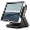
16. Replace the five screws that secure the display head to the housing. NOTE: Some models may have only four screws. The center screw shown below may not be included. Figure 2-31 Replacing the Display Head 17. Connect the MSR cable (1), place the MSR onto the side of the display head (2), and replace the two screws that hold the MSR in place (3). Figure 2-32 Replacing the MSR 18. Turn the unit over and onto its base. 19. Plug the power cord and all peripherals into the bottom I/O panel. 20. Replace the bottom I/O cover (see Replacing the Bottom I/O Cover on page 6). 21. Replace the drive cover (see Replacing the Drive Cover on page 8). 22. Plug in any peripherals that were unplugged from the side I/O panel. 23. Plug the power cord into an electrical outlet and press the power button. 26 Chapter 2 Hardware Upgrades ENWW
-
 1
1 -
2
-
3
-
4
-
5
-
6
-
7
-
8
-
9
-
10
-
11
-
12
-
13
-
14
-
15
-
16
-
17
-
18
-
19
-
20
-
21
-
22
-
23
-
24
-
25
-
26
-
 27
27 -
 28
28 -
 29
29 -
 30
30 -
 31
31 -
 32
32 -
 33
33 -
 34
34 -
 35
35 -
 36
36 -
 37
37 -
38
 |
 |
