HP ap5000 Hardware Reference Guide HP ap5000 All-In-One Point of Sale System - Page 29
CAUTION, Removing the Drive Cover, on Removing the Bottom I/O Cover - memory
 |
View all HP ap5000 manuals
Add to My Manuals
Save this manual to your list of manuals |
Page 29 highlights
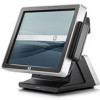
The memory modules are located on the system board behind the touch screen. You must remove the drive cover, remove the MSR, and disassemble the touch screen display head to access the memory. 1. Turn off the computer properly through the operating system, then turn off any external devices. 2. Disconnect the power cord from the power outlet. CAUTION: You must disconnect the power cord and wait approximately 30 seconds for the power to drain before adding or removing memory modules. Regardless of the power-on state, voltage is always supplied to the memory modules as long as the computer is plugged into an active AC outlet. Adding or removing memory modules while voltage is present may cause irreparable damage to the memory modules or system board. 3. Unplug all peripherals from the side I/O panel. 4. Remove the drive cover (see Removing the Drive Cover on page 8). 5. Remove the bottom I/O cover (see Removing the Bottom I/O Cover on page 6). 6. Unplug the power cord and all peripherals from the bottom I/O panel. 7. Tilt the touch screen all the way back to its horizontal position and lay the unit face down on a soft, clean, dry cloth to avoid scratching the touch screen. 8. To remove the MSR, remove the two screws that attach the MSR to the display head (1), lift the MSR off the display head (2), and unplug the cable attached to the underside of the MSR (3). NOTE: The screws may be covered by plugs that must be pried out before the screws can be removed. Figure 2-26 Removing the MSR ENWW Installing Additional Memory 23
-
 1
1 -
2
-
3
-
4
-
5
-
6
-
7
-
8
-
9
-
10
-
11
-
12
-
13
-
14
-
15
-
16
-
17
-
18
-
19
-
20
-
21
-
22
-
23
-
 24
24 -
 25
25 -
 26
26 -
 27
27 -
 28
28 -
 29
29 -
 30
30 -
 31
31 -
 32
32 -
 33
33 -
 34
34 -
35
-
36
-
37
-
38
 |
 |
