HP dv8000 HP Pavilion dv8200 Notebook PC, HP Pavilion dv8000 Notebook PC - Mai - Page 158
Due to the adhesive quality of the thermal paste located, between the heat sink and processor
 |
UPC - 654954100226
View all HP dv8000 manuals
Add to My Manuals
Save this manual to your list of manuals |
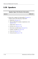
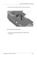
Page 158 highlights
Removal and Replacement Procedures 2. Turn the system board upside down with the expansion port 2 toward you. 3. Remove the four silver Phillips PM2.5×6.0 screws 1 that secure the heat sink to the system board. 4. Remove the heat sink 2. ✎ Due to the adhesive quality of the thermal paste located between the heat sink and processor, it may be necessary to move the heat sink from side to side to detach the heat sink from the processor. Removing the Heat Sink 5-68 Maintenance and Service Guide
-
 1
1 -
2
-
3
-
4
-
5
-
6
-
7
-
8
-
9
-
10
-
11
-
12
-
13
-
14
-
15
-
16
-
17
-
18
-
19
-
20
-
21
-
22
-
23
-
24
-
25
-
26
-
27
-
28
-
29
-
30
-
31
-
32
-
33
-
34
-
35
-
36
-
37
-
38
-
39
-
40
-
41
-
42
-
43
-
44
-
45
-
46
-
47
-
48
-
49
-
50
-
51
-
52
-
53
-
54
-
55
-
56
-
57
-
58
-
59
-
60
-
61
-
62
-
63
-
64
-
65
-
66
-
67
-
68
-
69
-
70
-
71
-
72
-
73
-
74
-
75
-
76
-
77
-
78
-
79
-
80
-
81
-
82
-
83
-
84
-
85
-
86
-
87
-
88
-
89
-
90
-
91
-
92
-
93
-
94
-
95
-
96
-
97
-
98
-
99
-
100
-
101
-
102
-
103
-
104
-
105
-
106
-
107
-
108
-
109
-
110
-
111
-
112
-
113
-
114
-
115
-
116
-
117
-
118
-
119
-
120
-
121
-
122
-
123
-
124
-
125
-
126
-
127
-
128
-
129
-
130
-
131
-
132
-
133
-
134
-
135
-
136
-
137
-
138
-
139
-
140
-
141
-
142
-
143
-
144
-
145
-
146
-
147
-
148
-
149
-
150
-
151
-
152
-
 153
153 -
 154
154 -
 155
155 -
 156
156 -
 157
157 -
 158
158 -
 159
159 -
 160
160 -
 161
161 -
 162
162 -
 163
163 -
164
-
165
-
166
-
167
-
168
-
169
-
170
-
171
-
172
-
173
-
174
-
175
-
176
-
177
-
178
-
179
-
180
-
181
-
182
-
183
-
184
-
185
-
186
-
187
-
188
-
189
-
190
-
191
-
192
-
193
-
194
-
195
-
196
-
197
-
198
-
199
-
200
-
201
-
202
-
203
-
204
-
205
-
206
-
207
-
208
-
209
-
210
-
211
-
212
-
213
-
214
-
215
-
216
-
217
-
218
-
219
-
220
-
221
-
222
-
223
-
224
-
225
-
226
-
227
-
228
-
229
-
230
-
231
-
232
-
233
-
234
-
235
-
236
-
237
-
238
-
239
-
240
-
241
-
242
-
243
-
244
-
245
-
246
-
247
-
248
-
249
-
250
-
251
-
252
-
253
-
254
-
255
-
256
-
257
-
258
-
259
-
260
-
261
-
262
-
263
-
264
 |
 |

5–68
Maintenance and Service Guide
Removal and Replacement Procedures
2.
Turn the system board upside down with the expansion port 2
toward you.
3. Remove the four silver Phillips PM2.5×6.0 screws
1
that
secure the heat sink to the system board.
4. Remove the heat sink
2
.
✎
Due to the adhesive quality of the thermal paste located
between the heat sink and processor, it may be necessary to
move the heat sink from side to side to detach the heat sink
from the processor.
Removing the Heat Sink