Hitachi 55HDT51 Owners Guide - Page 15
Connecting External Video Sources - avc
 |
View all Hitachi 55HDT51 manuals
Add to My Manuals
Save this manual to your list of manuals |
Page 15 highlights
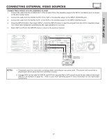
FIRST TIME USE CONNECTING EXTERNAL VIDEO SOURCES The exact arrangement you use to connect the VCR, camcorder, laserdisc player, DVD player, or HDTV Set Top Box to your Plasma TV is dependent on the model and features of each component. Check the owner's manual of each component for the location of video and audio inputs and outputs. The following connection diagrams are offered as suggestions. However, you may need to modify them to accommodate your particular assortment of components and features. For best performance, video and audio cables should be made from coaxial shielded wire. Before Operating External Video Source Connect an external source to one of the INPUT terminals, then press the INPUTS button to show the INPUTS menu. Use the CURSOR PAD to select the Antenna or Input of your choice. Then press the SELECT button to confirm your choice (see page 33). Photo Input Ant B Ant A Input 1 Input 2 Move SEL Sel. CONNECTING A MONAURAL AUDIO SOURCE TO INPUT1~INPUT5 1. Connect the cable from the VIDEO OUT of the VCR or the laserdisc player to the INPUT (VIDEO) jack, as shown on the AVC Center below. 2. Connect the cable from the AUDIO OUT of the VCR or the laserdisc player to the INPUT (MONO)/L(AUDIO) jack. 3. Press the INPUTS button, then select INPUT 3 from the INPUTS menu to view the program from the VCR or the laserdisc player. The VIDEO label disappears automatically after approximately four seconds. 4. Select Ant A or B from the INPUTS menu to return to the previous channel. Back of VCR AUDIO OUT VIDEO OUT VCR 15
-
 1
1 -
2
-
3
-
4
-
5
-
6
-
7
-
8
-
9
-
 10
10 -
 11
11 -
 12
12 -
 13
13 -
 14
14 -
 15
15 -
 16
16 -
 17
17 -
 18
18 -
 19
19 -
 20
20 -
21
-
22
-
23
-
24
-
25
-
26
-
27
-
28
-
29
-
30
-
31
-
32
-
33
-
34
-
35
-
36
-
37
-
38
-
39
-
40
-
41
-
42
-
43
-
44
-
45
-
46
-
47
-
48
-
49
-
50
-
51
-
52
-
53
-
54
-
55
-
56
-
57
-
58
-
59
-
60
-
61
-
62
-
63
-
64
-
65
-
66
-
67
-
68
-
69
-
70
-
71
-
72
-
73
-
74
-
75
-
76
-
77
-
78
-
79
-
80
-
81
-
82
-
83
-
84
-
85
-
86
-
87
-
88
-
89
-
90
-
91
-
92
-
93
-
94
-
95
-
96
-
97
-
98
-
99
-
100
 |
 |
