Husqvarna P-ZT6126 Owners Manual - Page 18
CONTROLS, Control Locations
 |
View all Husqvarna P-ZT6126 manuals
Add to My Manuals
Save this manual to your list of manuals |
Page 18 highlights
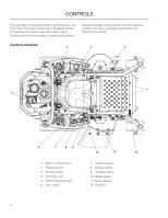
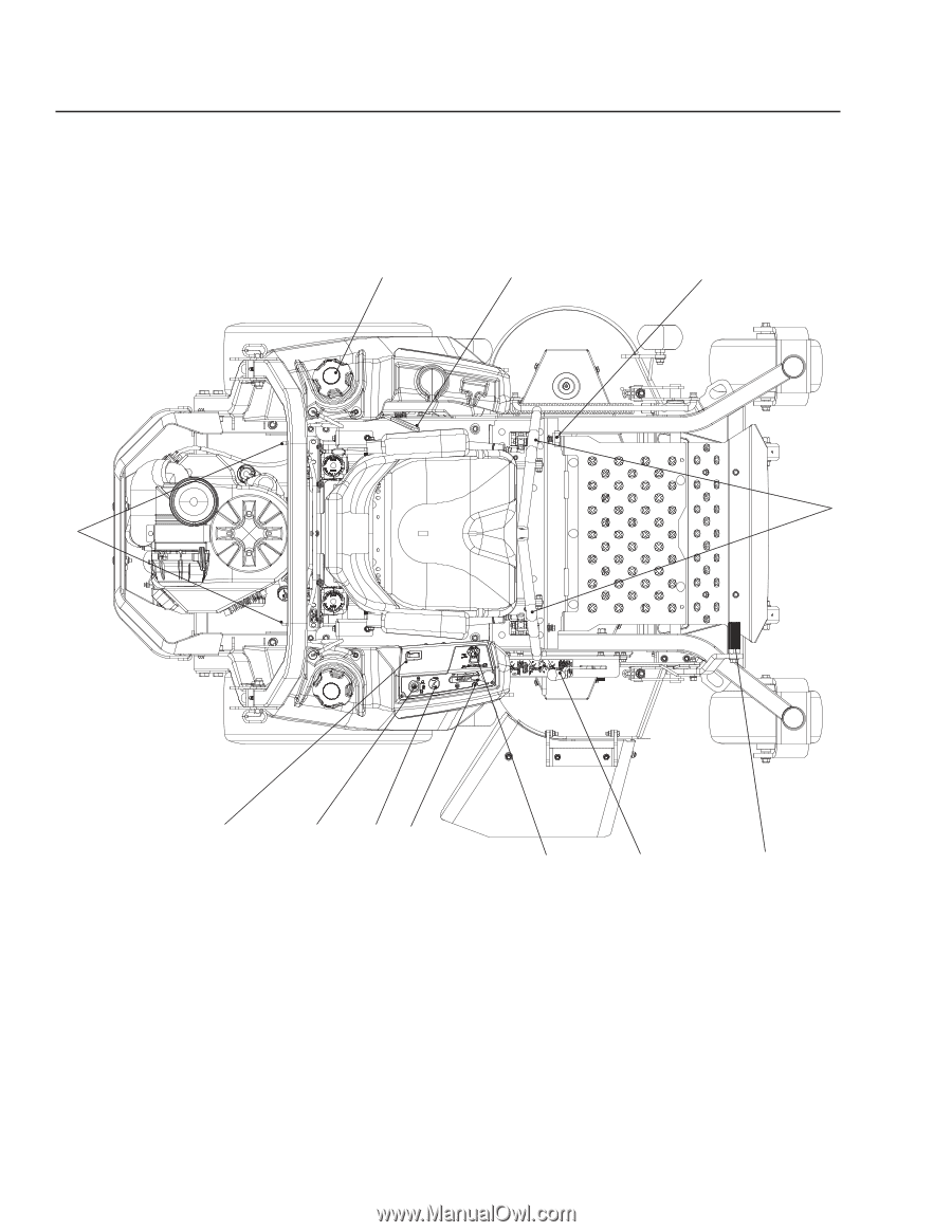
CONTROLS This operator's manual describes the Husqvarna Zero Turn Rider. The rider is fitted with a Briggs & Stratton or Kawasaki four-stroke overhead valve engine. Transmission from the engine is made via belt-driven hydraulic pumps. Using the left and right steering controls, the flow is regulated and thereby the direction and speed. Control Locations 4 3 2 1 5 6 7 89 10 12 13 1. Motion control levers 2. Tracking knob 3. Parking brake 4. Fuel tank - left 5. Hydro releases levers 6. Hour meter 7. Ignition switch 8. Choke control 9. Throttle control 10. Blade switch 11. Deck release 12. Deck lift 18
-
 1
1 -
2
-
3
-
4
-
5
-
6
-
7
-
8
-
9
-
10
-
11
-
12
-
 13
13 -
 14
14 -
 15
15 -
 16
16 -
 17
17 -
 18
18 -
 19
19 -
 20
20 -
 21
21 -
 22
22 -
 23
23 -
24
-
25
-
26
-
27
-
28
-
29
-
30
-
31
-
32
-
33
-
34
-
35
-
36
-
37
-
38
-
39
-
40
-
41
-
42
-
43
-
44
-
45
-
46
-
47
-
48
-
49
-
50
-
51
-
52
-
53
-
54
-
55
-
56
-
57
-
58
-
59
-
60
-
61
-
62
-
63
-
64
-
65
-
66
-
67
-
68
 |
 |
ContRols
18
This operator’s manual describes the Husqvarna Zero
Turn Rider. The rider is fitted with a Briggs & Stratton
or Kawasaki four-stroke overhead valve engine.
Transmission from the engine is made via belt-driven
hydraulic pumps. Using the left and right steering
controls, the flow is regulated and thereby the
direction and speed.
Control Locations
1
2
3
4
5
6
8
9
10
12
7
13
Motion control levers
1.
Tracking knob
2.
Parking brake
3.
Fuel tank - left
4.
Hydro releases levers
5.
Hour meter
6.
Ignition switch
7.
Choke control
8.
Throttle control
9.
Blade switch
10.
Deck release
11.
Deck lift
12.