Intel D875PBZ Product Guide
Intel D875PBZ - Desktop Board Motherboard Manual
 |
View all Intel D875PBZ manuals
Add to My Manuals
Save this manual to your list of manuals |
Intel D875PBZ manual content summary:
- Intel D875PBZ | Product Guide - Page 1
Intel® Desktop Board D875PBZ Product Guide Order Number: C24494-001 - Intel D875PBZ | Product Guide - Page 2
at any time, without notice. Desktop Board D875PBZ may contain design defects or errors known as errata which may cause the product to deviate from published specifications. Current characterized errata are available on request. Contact your local Intel sales office or your distributor to obtain the - Intel D875PBZ | Product Guide - Page 3
BIOS: instructions on how to update the BIOS. • 4 Using the BIOS Setup Program: contents of the BIOS Setup menus and submenus. • 5 Technical Reference: information about connectors and desktop board resources. • A Error Messages and Indicators: information about BIOS error messages and beep codes - Intel D875PBZ | Product Guide - Page 4
bytes) Megabit (1,048,576 bits) Megahertz (one million hertz) Box Contents • Intel Desktop Board • I/O shield • One IDE cable (ATA66/100) • Two SATA cables • One diskette drive cable • Quick Reference Guide • Configuration and battery caution statement label • Intel® Express Installer CD-ROM iv - Intel D875PBZ | Product Guide - Page 5
1 Desktop Board Features Supported Operating Systems 13 Desktop Board Components 14 Processor ...16 Main Memory ...17 Intel® 875P Chipset ...18 Input/Output (I/O) Controller 18 LAN Subsystem...18 LAN Subsystem Software 18 RJ-45 LAN Connector LEDs 19 Hi-Speed USB 2.0 Support 19 IDE Support...20 - Intel D875PBZ | Product Guide - Page 6
the Front Panel Header 44 Connecting the USB 2.0 Header 45 Connecting Hardware Control and Power Cables 46 Connecting Hardware Control Cables 47 Connecting Power Cables 47 Setting the BIOS Configuration Jumper Block 48 Clearing Passwords ...49 Replacing the Battery ...50 3 Updating the BIOS - Intel D875PBZ | Product Guide - Page 7
Menu ...86 5 Technical Reference Back Panel Connectors ...88 Add-In Card and Peripheral Interface Connectors 89 Desktop Board Resources 90 Memory Map ...90 DMA Channels ...90 Interrupts ...91 A Error Messages and Indicators BIOS Beep Codes ...93 BIOS Error Messages...94 B Regulatory Compliance - Intel D875PBZ | Product Guide - Page 8
48 16. Replacing the Battery...52 17. Back Panel Connectors...88 18. Add-In Card and Peripheral Interface Connectors 89 Tables 1. Feature Summary ...11 2. Supported Processors...16 3. RJ-45 10/100/1000 Gigabit Ethernet LAN Connector LEDs 19 4. Front Panel Header (J8J3 44 5. USB 2.0 Header (J8J1 - Intel D875PBZ | Product Guide - Page 9
Contents 29. Boot Device Priority Submenu 82 30. Hard Disk Drives Submenu 83 31. Removable Devices Submenu 84 32. ATAPI CD-ROM Drives Submenu 85 33. Exit Menu...86 34. System Memory Map ...90 35. DMA Channels...90 36. Interrupts...91 37. Beep Codes ...93 38. BIOS Error Messages ...94 39. Safety - Intel D875PBZ | Product Guide - Page 10
Intel Desktop Board D875PBZ Product Guide x - Intel D875PBZ | Product Guide - Page 11
AGP 8x connector • Up to eight USB 2.0 ports Six ports routed to the back panel Two ports routed to the USB header • Two Serial ATA channels (SATA), via the native SATA controller, one device per channel • SATA RAID 0 (Windows* XP only) • Two IDE interfaces with ATA-66/100 support • One diskette - Intel D875PBZ | Product Guide - Page 12
flash memory • Support for SMBIOS • Intel® Rapid BIOS Boot • Intel® Express BIOS Update Power Management • Support for Advanced Configuration and Power Interface (ACPI) and Advanced Power Management (APM) • Suspend to RAM (STR) • Wake on USB, PCI, RS-232, PS/2, LAN, and front panel Hardware - Intel D875PBZ | Product Guide - Page 13
Supported Operating Systems The desktop board supports the following operating systems: • Microsoft Windows 2000 • Microsoft Windows XP • Microsoft Windows Me • Microsoft Windows 98 SE Desktop Board Features 13 - Intel D875PBZ | Product Guide - Page 14
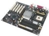
Intel Desktop Board D875PBZ Product Guide Desktop Board Components Figure 1 shows the approximate location of the major components on Desktop Board D875PBZ. USB 2.0 Devices AB RJ45 USB 2.0 Devices C D X E W F G V U H T S Q O ML K R PN J I Figure 1. Desktop Board Components - Intel D875PBZ | Product Guide - Page 15
Intel 82875P (MCH) H DIMM sockets I Main power connector J Diskette drive connector K Primary IDE connector L Secondary IDE connector M SCSI LED header N Front chassis fan header (fan speed control) O Serial ATA headers P BIOS configuration jumper Q USB 2.0 header R Front panel - Intel D875PBZ | Product Guide - Page 16
Intel Desktop Board D875PBZ Product Guide Processor CAUTION Failure to use an ATX12V power supply, or not connecting the 12 V processor core voltage power supply connector to Desktop Board D875PBZ may result in damage to the desktop board and/or power supply. Desktop Board D875PBZ supports a - Intel D875PBZ | Product Guide - Page 17
the screen at power up. The BIOS will attempt to configure the memory controller for normal operation. The desktop board supports system memory as defined below: • Up to four dual channel 184-pin Double Data Rate (DDR) SDRAM DIMMs connectors with gold-plated contacts. Supported memory configurations - Intel D875PBZ | Product Guide - Page 18
link to the memory controller hub with CSA • Configurable EEPROM that contains the MAC address • Support for: ASF 2.0 RJ-45 connector with status indicator LEDs LAN Subsystem Software Go to the following link for LAN software and drivers: http://support.intel.com/support/motherboards/desktop 18 - Intel D875PBZ | Product Guide - Page 19
prior to operating system and driver initialization. The desktop board supports up to eight USB 2.0 ports via ICH5R; six ports routed to the back panel and two routed to the internal USB 2.0 header. USB 2.0 ports are backward compatible with USB 1.1 devices. USB 1.1 devices will function normally at - Intel D875PBZ | Product Guide - Page 20
the exchange of data between the processor and SATA devices. The controller supports: • Transfer rate of 150 MB/sec • Up to two SATA devices • RAID 0 (striping) support (for Windows XP only) • PIO and DMA modes Accelerated Graphics Port (AGP) NOTE The AGP connector is keyed for 1.5 V and 0.8 V AGP - Intel D875PBZ | Product Guide - Page 21
ATA-66/100 peripheral device • An ATA-66/100 compatible cable • ATA-66/100 operating system device drivers Security Passwords The BIOS includes security features that restrict whether the BIOS Setup program can be accessed and who can boot the computer. A supervisor password and a user password can - Intel D875PBZ | Product Guide - Page 22
Intel Desktop Board D875PBZ Product Guide Power Management Features Power management is implemented at several levels, including: • Software support through Advanced Configuration and Power Interface (ACPI) and Advanced Power Management (APM) • Hardware support: Suspend to RAM (Instantly Available - Intel D875PBZ | Product Guide - Page 23
of the power connectors. Fan Connectors The desktop board has three chassis fan connectors and one processor fan connector. See Figure 14 on page 46 for the location of the fan connectors. Related Links: Go to page 46 for the location of the fan headers. Fan Speed Control (Intel® Precision Cooling - Intel D875PBZ | Product Guide - Page 24
Intel Desktop Board D875PBZ Product Guide fans connected to the front and rear chassis fan connectors. The processor fan connector is not controlled. The fan speed control feature can be disabled in the BIOS, resulting in the chassis fans always operating at full speed. This feature should be - Intel D875PBZ | Product Guide - Page 25
provides audible error code (beep code) information during the Power-On Self-Test (POST). Battery A battery on the desktop board keeps the values in CMOS RAM and the clock current when the computer is turned off. See Chapter 2 starting on page 27 for instructions on how to replace the battery. Real - Intel D875PBZ | Product Guide - Page 26
Intel Desktop Board D875PBZ Product Guide 26 - Intel D875PBZ | Product Guide - Page 27
the desktop board • Install and remove a processor and memory • Install and remove an AGP card • Connect the IDE and Serial ATA cables • Configure Intel RAID Technology • Connect internal headers • Connect fans and power cables • Set the BIOS configuration jumper • Clear passwords • Replace the - Intel D875PBZ | Product Guide - Page 28
Intel Desktop Board D875PBZ Product Guide Installation Precautions When you install and test the Intel desktop board, observe all warnings and cautions in the installation instructions. To avoid injury, be careful of: • Sharp pins on connectors • Sharp pins on printed circuit assemblies • Rough - Intel D875PBZ | Product Guide - Page 29
within the computer is less than the output current rating of each of the power supplies output circuits. Place Battery Marking There is insufficient space on this Desktop Board to provide instructions for replacing and disposing of the Lithium ion coin cell battery. For system safety certification - Intel D875PBZ | Product Guide - Page 30
Intel Desktop Board D875PBZ Product Guide Use Only for Intended Applications All Intel Desktop Boards are evaluated as Information Technology 97. Installing the I/O Shield The desktop board comes with an I/O shield. When installed in the chassis, the shield blocks radio frequency transmissions - Intel D875PBZ | Product Guide - Page 31
or equipment damage. Read the safety instruction in "Before You Begin" on page 27 of this chapter. Refer to your chassis manual for instructions on installing and removing the desktop board. Figure 4 shows the location of the 10 mounting holes for Desktop Board D875PBZ. OM15683 Figure 4. Location of - Intel D875PBZ | Product Guide - Page 32
Installing the Processor Fan Heat Sink Desktop Board D875PBZ has an integrated processor fan heat sink retention mechanism (RM). For instructions on how to attach the processor fan heat sink to the integrated processor fan heat sink RM, refer to the boxed processor manual or the Intel World Wide - Intel D875PBZ | Product Guide - Page 33
Connecting the Processor Fan Heat Sink Cable to the Processor Fan Connector Removing the Processor Go to the following link or refer to the processor installation manual for instruction on how to remove the processor fan heat sink and processor: http://support.intel.com/support/processors/pentium4 - Intel D875PBZ | Product Guide - Page 34
SDRAM memory specifications, the board requires DIMMs that support the Serial Presence Detect (SPD) data structure. You can access the PC Serial Presence Detect Specification at: http://www.intel.com/technology/memory/pcsdram/spec/ Desktop Board D875PBZ has four dual channel 184-pin DIMM sockets - Intel D875PBZ | Product Guide - Page 35
Installing and Replacing Desktop Board Components Installing DIMMs Before installing DIMMs, read and follow these guidelines for dual channel configuration. NOTE Performance Acceleration Technology (PAT) requires a processor with an 800 MHz FSB and DDR400 memory. Install a matched pair of DIMMs - Intel D875PBZ | Product Guide - Page 36
Intel Desktop Board D875PBZ Product Guide CAUTION Install memory in the DIMM sockets prior to installing the AGP video card to avoid interference with the memory the DIMMs. 11. Replace the computer's cover and reconnect the AC power cord. Removing DIMMs To remove a memory module, follow these steps - Intel D875PBZ | Product Guide - Page 37
of the power supply, certain board components and/or traces may be damaged. NOTE The AGP connector is keyed for 1.5 V and 0.8 V AGP cards only. Do not attempt to install a legacy 3.3 V AGP card. The AGP connector is not mechanically compatible with legacy 3.3 V AGP cards. The AGP connector supports - Intel D875PBZ | Product Guide - Page 38
Intel Desktop Board D875PBZ Product Guide Removing the AGP Card Follow these instructions to remove the AGP card from the RM: 1. Observe the precautions in "Before You Begin" on page 27. 2. Remove the screw (B) that secures the card's metal bracket (A) to the chassis back panel. 3. Push back on the - Intel D875PBZ | Product Guide - Page 39
Replacing Desktop Board Components Connecting the IDE Cable The Intel® boxed desktop board package includes an IDE cable. The cable can connect two drives to the desktop board. The cable supports connector to the Intel desktop board. • Attach the cable end with the two closely spaced connectors - Intel D875PBZ | Product Guide - Page 40
Intel Desktop Board D875PBZ Product Guide Connecting the Serial ATA Cable NOTE All SATA and IDE devices are enabled by default support up to six devices. Windows 98 and Windows Me may require using the Legacy ATA/IDE configuration mode to only enable four SATA/IDE devices. This mode can be changed - Intel D875PBZ | Product Guide - Page 41
Microsoft Windows XP only. Configuring the BIOS for Intel RAID Technology for Serial ATA The SoftRAID option must be enabled in BIOS before the system can load the option ROM code for Intel RAID. 1. Enter the BIOS Setup program by pressing the key after the Power-On-Self-Test (POST) memory test - Intel D875PBZ | Product Guide - Page 42
of RAID when upgrading to a second Serial ATA drive. 1. The BIOS must be configured for RAID before installing Windows XP on the single Serial ATA drive. Refer to section "Configuring the BIOS for Intel RAID Technology for Serial ATA" to properly configure the BIOS. 2. Install the Intel RAID driver - Intel D875PBZ | Product Guide - Page 43
and Replacing Desktop Board Components Upgrading to Serial ATA RAID 0 Configuration from a Single Drive Configuration 1. Install the second Serial ATA drive in the system. Refer to section "Connecting the Serial ATA (SATA) Cable". 2. Start the system and boot into Windows XP. 3. Launch the Intel - Intel D875PBZ | Product Guide - Page 44
Guide Connecting Internal Headers Before connecting cables to the internal headers, observe the precautions in "Before You Begin" on page 27. 3 1 J9J1 A 9 8 7 6 5 4 3 2 1 J8J3 B 10 8 7 6 5 4 3 2 1 J8J1 C Item A B C Description Alternate power/sleep LED Front panel USB - Intel D875PBZ | Product Guide - Page 45
and Replacing Desktop Board Components Connecting the USB 2.0 Header Before connecting the USB 2.0 header, observe the precautions in "Before You Begin" on page 27. Figure 13 shows the location of the USB 2.0 header. Table 5 shows the pin assignments for the USB 2.0 header. Table 5. USB 2.0 Header - Intel D875PBZ | Product Guide - Page 46
Intel Desktop Board D875PBZ Product Guide Connecting Hardware Control and Power Cables Figure 14 shows the location of the hardware control (fans and chassis intrusion) headers and power supply connectors. Chassis rear fan 1 J5B1 12 V Processor core voltage connector 1 2 VREG fan 1 J6B1 - Intel D875PBZ | Product Guide - Page 47
to the board fan headers. Connect the chassis intrusion cable to its respective header on the board. See Figure 14 for header locations. Connecting Power Cables CAUTION Failure to use an ATX12V power supply, or not connecting the 12 V processor core voltage power supply connector to the desktop - Intel D875PBZ | Product Guide - Page 48
Intel Desktop Board D875PBZ Product Guide Setting the BIOS Configuration Jumper Block CAUTION Always turn off the power and unplug the power cord from the computer before changing the jumper. Moving the jumper with the power on may result in unreliable computer operation. The location of the desktop - Intel D875PBZ | Product Guide - Page 49
below. 13 6. Replace the cover, plug in the computer, turn on the computer, and allow it to boot. 7. The computer starts the Setup program. Setup displays the Maintenance menu. 8. Use the arrow keys to select Clear Passwords. Press and Setup displays a pop-up screen - Intel D875PBZ | Product Guide - Page 50
Board D875PBZ Product Guide Replacing the Battery A coin-cell battery (CR2032) powers the real-time clock and CMOS memory. When the computer is not plugged into a wall socket, the battery has an estimated life of three years. When the computer is plugged in, the standby current from the power supply - Intel D875PBZ | Product Guide - Page 51
Installing and Replacing Desktop Board Components AVVERTIMENTO Esiste il pericolo di un esplosione se la pila non viene sostituita in modo corretto. Utilizzare solo pile uguali o di tipo equivalente a quelle - Intel D875PBZ | Product Guide - Page 52
Intel Desktop Board D875PBZ Product Guide To replace the battery, follow these steps: 1. Observe the precautions in "Before You Begin" on page 27. 2. Turn off all peripheral devices connected to the computer. Disconnect the computer's power cord from the AC power source (wall outlet or power adapter - Intel D875PBZ | Product Guide - Page 53
update the BIOS with the Intel Express BIOS Update utility: 1. Go to the Intel World Wide Web site: http://support.intel.com/support/motherboards/desktop/ 2. Navigate to the Desktop Board D875PBZ page and click the Express BIOS Update utility file for the Desktop Board D875PBZ BIOS. 3. Download the - Intel D875PBZ | Product Guide - Page 54
Board D875PBZ page on the Intel World Wide Web site: http://support.intel.com/support/motherboards/desktop NOTE Review the instructions distributed with the update utility before attempting a BIOS update. The Iflash BIOS update utility allows you to: • Update the BIOS in flash memory • Update - Intel D875PBZ | Product Guide - Page 55
recover the BIOS if an update fails. The following procedure uses recovery mode for the Setup program. See page 48 for more information on Setup modes. NOTE Because of the small amount of code available in the boot block area, there is no video support. You will not see anything on the screen during - Intel D875PBZ | Product Guide - Page 56
Intel Desktop Board D875PBZ Product Guide 56 - Intel D875PBZ | Product Guide - Page 57
system boot begins. NOTE The BIOS Setup menus described in this section may not show the latest settings. For the latest BIOS settings, refer to the Intel Desktop Board D875PBZ Technical Product Specification or the Intel World Wide Web site: http://support.intel.com/support/motherboards/desktop - Intel D875PBZ | Product Guide - Page 58
the Wired for Management Boot Integrity Service • Cancel (BIS) credentials. CPU Stepping Signature No options Displays processor's Stepping Signature. CPU Microcode Update Revision No options Displays processor's Microcode Update Revision. * For information about the BIS, refer to the Intel Web - Intel D875PBZ | Product Guide - Page 59
Security Power Boot Exit BIOS Version BZ87510A.86A.xxxx.xxx Processor Type Hyper-Threading Technology Processor Speed System Bus Speed System Memory Speed Intel(R) Pentium(R) 4 [Enabled] X.XX GHz XXX MHz XXX MHz Cache RAM XXX KB Total Memory Memory Mode Memory Channel A Slot 0 Memory Channel - Intel D875PBZ | Product Guide - Page 60
Intel Desktop Board D875PBZ Product Guide Advanced Menu Main Advanced Security Power Boot Exit Setup Warning: Setting items on this screen to incorrect values may cause your system to malfunction! ` PCI Configuration ` Boot Configuration ` Peripheral Configuration ` IDE Configuration ` Diskette - Intel D875PBZ | Product Guide - Page 61
Using the BIOS Setup Program PCI Configuration Submenu Main Advanced Security Power Boot Exit PCI Configuration PCI Slot 1 IRQ Priority PCI Slot 2 IRQ Priority PCI Slot 3 IRQ Priority PCI Slot 4 IRQ Priority PCI Slot 5 IRQ Priority [Auto] m o n p Enter F1 P9 F10 ESC Select Screen Select Item - Intel D875PBZ | Product Guide - Page 62
Intel Desktop Board D875PBZ Product Guide Boot Configuration Submenu Main Advanced Security Power Boot Exit Boot Configuration Plug & Play O/S Numlock [No] [On] m o n p Enter F1 P9 F10 ESC Select Screen Select Item Select ` Sub-Menu General Help Setup Defaults Save and Exit Exit The submenu - Intel D875PBZ | Product Guide - Page 63
Using the BIOS Setup Program Peripheral Configuration Submenu Main Advanced Security Power Boot Exit Peripheral Configuration Serial Port A Parallel Port Mode LAN Device [Auto] [Auto] [Bi-directional] [Enabled] m o n p Enter F1 P9 F10 ESC Select Screen Select Item Select ` Sub-Menu General Help - Intel D875PBZ | Product Guide - Page 64
Intel Desktop Board D875PBZ Product Guide Table 14. Peripheral LAN) • 378 (default) • 278 • IRQ 5 • IRQ 7 (default) • Disabled • Enabled (default) Description Selects the mode for the parallel port. Not available if the parallel port is disabled. Output Only operates in AT*-compatible - Intel D875PBZ | Product Guide - Page 65
Using the BIOS Setup Program IDE Configuration Submenu Main Advanced Security Power Boot Exit IDE Configuration ATA/IDE Configuration SATA OOB Workaround PCI IDE Bus Master Hard Disk Pre-Delay SoftRAID Support [Enhanced] [Enabled] [Enabled] [Disabled] [Disabled] ` [SATA Port-0 : ` [SATA Port - Intel D875PBZ | Product Guide - Page 66
Intel Desktop Board D875PBZ Product Guide SATA and PATA Submenus Main Advanced Security Power Boot Exit ` [SATA Port-0 : Xxxxxxxxx ] Type Maximum Capacity [Auto] [Auto] Configuration Options Selected By BIOS LBA Mode : Block Mode : PIO Mode : Ultra DMA : Cable Detected : [Supported] 16 - Intel D875PBZ | Product Guide - Page 67
Using the BIOS Setup Program Table 16. Primary/Secondary IDE Master/Slave Submenus (continued) Feature DMA Mode S.M.A.R.T. Cable Detected (Note) Options • Auto (default) • SWDMA 0 • SWDMA 1 • SWDMA 2 • MWDMA 0 • MWDMA 1 • - Intel D875PBZ | Product Guide - Page 68
Intel Desktop Board D875PBZ Product Guide Diskette Configuration Submenu Main Advanced Security Power Boot Diskette Configuration Diskette Controller Floppy A Diskette Write Protect [Enabled] [1.44/1.25MB 3½"] [Disabled] Exit m o n p Enter F1 P9 F10 ESC Select Screen Select Item Select ` Sub - Intel D875PBZ | Product Guide - Page 69
the BIOS Setup Program Event Log Configuration Submenu Main Advanced Security Power Boot Event Log Configuration Event Log View Event Log Clear Event Log Event Logging ECC Event Logging [Space Available] [Enabled] [Enabled] Exit Mark Events As Read m o n p Enter F1 P9 F10 ESC Select Screen - Intel D875PBZ | Product Guide - Page 70
Intel Desktop Board D875PBZ Product Guide Video Configuration Submenu Main Advanced Security Power Boot Exit Video Configuration AGP Aperture Size Primary Video Adapter [ 64MB] [AGP] m o n p Enter F1 P9 F10 ESC Select Screen Select Item Select ` Sub-Menu General Help Setup Defaults Save - Intel D875PBZ | Product Guide - Page 71
Using the BIOS Setup Program USB Configuration Submenu Main Advanced Security Power Boot Exit USB Configuration High-Speed USB Legacy USB Support [Enabled] [Enabled] m o n p Enter F1 P9 F10 ESC Select Screen Select Item Select ` Sub-Menu General Help Setup Defaults Save and Exit Exit The - Intel D875PBZ | Product Guide - Page 72
Intel Desktop Board D875PBZ Product Guide Chipset Configuration Submenu Main Advanced Security Power Boot Exit Chipset Configuration Setup Warning: Setting items on this screen to incorrect values may cause your system to malfunction! ISA Enable Bit PCI Latency Timer IOAPIC Enable Watchdog - Intel D875PBZ | Product Guide - Page 73
according to the memory detected. Manual - Aggressive selects the most aggressive user defined timings. Manual - User Defined allows manual override of detected SDRAM settings. Controls Command Per Clock/1n rule mode. When enabled, allows DRAM controller to attempt Chip Select assertions in - Intel D875PBZ | Product Guide - Page 74
Intel Desktop Board D875PBZ Product Guide Fan Control Submenu Main Advanced Security Power Boot Exit Fan Control Configuration Setup Warning: These options will not take effect until power has been completely removed from the system. After saving the BIOS settings and turning the system off, - Intel D875PBZ | Product Guide - Page 75
44oC/111oF 37oC/98oF 35oC/95oF Processor Fan Speed Rear Fan Speed (J1B1) VREG Fan Speed (J5B1) Front Fan Speed 2394 RPM 0 RPM 0 RPM 0 RPM +1.5Vin Vccp +3.3Vin +5Vin 12Vin 1.480 V 1.447 V 3.258 V 5.026 V 11.625 V m o n p Enter F1 P9 F10 ESC Select Screen Select Item Select ` Sub-Menu General - Intel D875PBZ | Product Guide - Page 76
Intel Desktop Board D875PBZ Product Guide Security Menu Main Advanced Security Power Boot Exit Supervisor Password : User Password : Set Supervisor Password Set User Password Not Installed Not Installed Chassis Intrusion [Disabled] m o n p Enter F1 P9 F10 ESC Select Screen Sets BIOS Setup - Intel D875PBZ | Product Guide - Page 77
BIOS Setup Program Power Menu Main Advanced Security Power Boot Exit APM ACPI After Power Failure [Last State] The options below are not related to ACPI and may be ignored when shutting down using an ACPI OS. Wake on PCI PME [Stay Off] m o n p Enter F1 P9 F10 ESC Select Screen Select - Intel D875PBZ | Product Guide - Page 78
Intel Desktop Board D875PBZ Product Guide APM Submenu Main Advanced Security Power Boot Exit APM Standby Time Out Suspend Power Saving Type Suspend Time Out Power Button Mode Video power Down Mode Hard Disk Power to Stop Grant or Quick Start Power State. S1 : Maintains POS Powered On Suspend - Intel D875PBZ | Product Guide - Page 79
Using the BIOS Setup Program Table 26. APM Submenu (continued) Feature Hard Disk Time Out (Min) Options • Disabled (default) • 1 • 2 • 3 • 4 • 5 • 6 • 7 • 8 • 9 • 10 • 11 • 12 • 13 • 14 • 15 Description Specifies the hard disk time out time. 79 - Intel D875PBZ | Product Guide - Page 80
Intel Desktop Board D875PBZ Product Guide ACPI Submenu Main Advanced Security Power Boot Exit Advanced Configuration and Power Interface ACPI Suspend State Wake on LAN from S5 [S1 State] [Stay Off] S1 is the safest mode but consumes more power. S3 consumes low power but drivers may not support - Intel D875PBZ | Product Guide - Page 81
the boot features and the boot sequence. Table 28. Boot Menu Feature Silent Boot Intel Rapid BIOS Boot Scan User Flash Area PXE Boot to LAN USB Boot Boot Device Priority Hard Disk Drives Removable Devices ATAPI CD-ROM Drives Options Description • Disabled Disabled displays normal POST messages - Intel D875PBZ | Product Guide - Page 82
Intel Desktop Board D875PBZ Product Guide Boot Device Priority Submenu Main Advanced Security Power Boot Exit 1st Boot Device 2nd Boot Device 3rd Boot Device [1st FLOPPY DRIVE] [xxxxxxxxxxx] [xxxxxxxxxxx] Specifies the boot sequence from the available devices. A device enclosed in parenthesis - Intel D875PBZ | Product Guide - Page 83
with or . 2. Press to set the selection as the intended boot device. Note: This boot device submenu appears only if at least one boot device of this type is installed. This list will display up to 12 hard disk drives, the maximum number of hard disk drives supported by the BIOS. 83 - Intel D875PBZ | Product Guide - Page 84
Intel Desktop Board D875PBZ Product Guide Removable Devices Submenu Main Advanced Security Power Boot Exit 1st Drive [1st FLOPPY DRIVE] Specifies the boot sequence from the available devices. Select the boot device with UpArrow or DownArrow key. Press Enter to set the selections as the intended - Intel D875PBZ | Product Guide - Page 85
or . 2. Press to set the selection as the intended boot device. Note: This boot device submenu appears only if at least one boot device of this type is installed. This list will display up to four ATAPI CD-ROM drives, the maximum number of ATAPI CD-ROM drives supported by the BIOS. 85 - Intel D875PBZ | Product Guide - Page 86
Intel Desktop Board D875PBZ Product Guide Exit Menu Main Advanced Security Power Boot Exit Exit Saving Changes Exit Discarding Changes Load Optimal Defaults Load Custom Defaults Save Custom Defaults Discard Changes m o n p Enter F1 P9 F10 ESC Select Screen Select Item Select ` Sub-Menu General - Intel D875PBZ | Product Guide - Page 87
the location of the: • Back panel connectors • Add-in board and peripheral interface connectors CAUTION Many of the midboard and front panel connectors provide operating voltage (+5 V dc and +12 V dc, for example) to devices inside the computer chassis, such as fans and internal peripherals. These - Intel D875PBZ | Product Guide - Page 88
Intel Desktop Board D875PBZ Product Guide Back Panel Connectors NOTE The line out connector, located on the back panel, is designed to power either headphones or amplified speakers only. Poor audio quality may occur if passive (non-amplified) speakers are connected to this output. Figure 17 shows - Intel D875PBZ | Product Guide - Page 89
PCI bus add-in card and peripheral interface connectors for the desktop board. A BCDE F J I H G OM15680 Item A B C D E Description PCI bus add-in card connector 5 PCI bus add-in card connector 4 PCI bus add-in card connector 3 PCI bus add-in card connector 2 (SMBus routed) PCI bus add-in card - Intel D875PBZ | Product Guide - Page 90
Intel Desktop Board D875PBZ Product Guide Desktop Board Resources Memory Map Table 34. System Memory Map Address Range (decimal) Address Range (hex) 1024 K - 4194304 K 100000 - FFFFFFFF 960 K - 1024 K F0000 - FFFFF 896 K - 960 K 800 K - 896 K E0000 - EFFFF C8000 - DFFFF 640 K - 800 K - Intel D875PBZ | Product Guide - Page 91
, keyboard buffer full 2 Reserved, cascade interrupt from slave PIC 3 COM2* 4 COM1* 5 LPT2 (Plug and Play option) / ** 6 Floppy drive controller 7 LPT1* 8 Real time clock 9 ** 10 ** 11 ** 12 Onboard mouse port (if present, else user available) 13 Reserved, math coprocessor - Intel D875PBZ | Product Guide - Page 92
Intel Desktop Board D875PBZ Product Guide 92 - Intel D875PBZ | Product Guide - Page 93
A Error Messages and Indicators Desktop Board D875PBZ reports POST errors in two ways: • By sounding a beep code • By displaying an error message on the monitor BIOS Beep Codes The BIOS beep codes are listed in Table 37. The BIOS also issues a beep code (one long tone followed by two short tones) - Intel D875PBZ | Product Guide - Page 94
Intel Desktop Board D875PBZ Product Guide BIOS Error Messages When a recoverable error occurs during the POST, the BIOS displays an error message describing the problem. Table 38. BIOS Error Messages Error Message Explanation GA20 Error An error occurred with Gate-A20 when switching to - Intel D875PBZ | Product Guide - Page 95
On Board Parity Error Parity Error NVRAM / CMOS / PASSWORD cleared by Jumper Pressed Explanation Memory size has decreased since the last boot. If no memory was removed, then memory may be bad. Memory size has increased since the last boot. If no memory was added, there may be a problem - Intel D875PBZ | Product Guide - Page 96
Intel Desktop Board D875PBZ Product Guide 96 - Intel D875PBZ | Product Guide - Page 97
of Nordic deviations to EN 60950. (Norway, Sweden, Denmark, and Finland) EMC Regulations Desktop Board D875PBZ complies with the EMC regulations stated in Table 40 when correctly installed in a compatible host system. Table 40. EMC Regulations Regulation FCC Class B ICES-003 (Class B) EN55022 - Intel D875PBZ | Product Guide - Page 98
Intel Desktop Board D875PBZ Product Guide Product Certification Markings Desktop Board D875PBZ has the following product certification markings (tick) mark (component side), followed by Intel supplier code number, N-232. • Printed wiring board manufacturer's recognition mark: consists of a unique UL
-
 1
1 -
 2
2 -
 3
3 -
 4
4 -
 5
5 -
 6
6 -
 7
7 -
8
-
9
-
10
-
11
-
12
-
13
-
14
-
15
-
16
-
17
-
18
-
19
-
20
-
21
-
22
-
23
-
24
-
25
-
26
-
27
-
28
-
29
-
30
-
31
-
32
-
33
-
34
-
35
-
36
-
37
-
38
-
39
-
40
-
41
-
42
-
43
-
44
-
45
-
46
-
47
-
48
-
49
-
50
-
51
-
52
-
53
-
54
-
55
-
56
-
57
-
58
-
59
-
60
-
61
-
62
-
63
-
64
-
65
-
66
-
67
-
68
-
69
-
70
-
71
-
72
-
73
-
74
-
75
-
76
-
77
-
78
-
79
-
80
-
81
-
82
-
83
-
84
-
85
-
86
-
87
-
88
-
89
-
90
-
91
-
92
-
93
-
94
-
95
-
96
-
97
-
98
 |
 |
Intel
®
Desktop Board
D875PBZ Product Guide
Order Number:
C24494-001