Intel D875PBZ Product Guide - Page 45
Connecting the USB 2.0 Header, Before You Begin
 |
View all Intel D875PBZ manuals
Add to My Manuals
Save this manual to your list of manuals |
Page 45 highlights
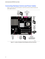
Installing and Replacing Desktop Board Components Connecting the USB 2.0 Header Before connecting the USB 2.0 header, observe the precautions in "Before You Begin" on page 27. Figure 13 shows the location of the USB 2.0 header. Table 5 shows the pin assignments for the USB 2.0 header. Table 5. USB 2.0 Header (J8J1) USB Port A Pin Signal name 1 Power 3 D- 5 D+ 7 Ground 9 Key Note: USB ports may be assigned as needed. USB Port B Pin Signal name 2 Power 4 D- 6 D+ 8 Ground 10 No connect 45
-
 1
1 -
2
-
3
-
4
-
5
-
6
-
7
-
8
-
9
-
10
-
11
-
12
-
13
-
14
-
15
-
16
-
17
-
18
-
19
-
20
-
21
-
22
-
23
-
24
-
25
-
26
-
27
-
28
-
29
-
30
-
31
-
32
-
33
-
34
-
35
-
36
-
37
-
38
-
39
-
 40
40 -
 41
41 -
 42
42 -
 43
43 -
 44
44 -
 45
45 -
 46
46 -
 47
47 -
 48
48 -
 49
49 -
 50
50 -
51
-
52
-
53
-
54
-
55
-
56
-
57
-
58
-
59
-
60
-
61
-
62
-
63
-
64
-
65
-
66
-
67
-
68
-
69
-
70
-
71
-
72
-
73
-
74
-
75
-
76
-
77
-
78
-
79
-
80
-
81
-
82
-
83
-
84
-
85
-
86
-
87
-
88
-
89
-
90
-
91
-
92
-
93
-
94
-
95
-
96
-
97
-
98
 |
 |

Installing and Replacing Desktop Board Components
45
Connecting the USB 2.0 Header
Before connecting the USB 2.0 header, observe the precautions in
“
Before You Begin
”
on page 27.
Figure 13 shows the location of the USB 2.0 header.
Table 5 shows the pin assignments for the
USB 2.0 header.
Table 5.
USB 2.0 Header (J8J1)
USB Port A
USB Port B
Pin
Signal name
Pin
Signal name
1
Power
2
Power
3
D-
4
D-
5
D+
6
D+
7
Ground
8
Ground
9
Key
10
No connect
Note:
USB ports may be assigned as needed.