Intel D875PBZ Product Guide - Page 44
Connecting Internal Headers, Connecting the Front Panel Header
 |
View all Intel D875PBZ manuals
Add to My Manuals
Save this manual to your list of manuals |
Page 44 highlights
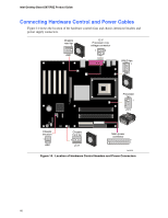
Intel Desktop Board D875PBZ Product Guide Connecting Internal Headers Before connecting cables to the internal headers, observe the precautions in "Before You Begin" on page 27. 3 1 J9J1 A 9 8 7 6 5 4 3 2 1 J8J3 B 10 8 7 6 5 4 3 2 1 J8J1 C Item A B C Description Alternate power/sleep LED Front panel USB 2.0 Figure 13. Location of Internal Headers OM15681 Connecting the Front Panel Header Before connecting the front panel header, observe the precautions in "Before You Begin" on page 27. Figure 13 shows the location of the front panel header. Table 4 shows the pin assignments for the front panel header. Table 4. Front Panel Header (J8J3) Pin Signal In/Out Description Hard Drive Activity LED Pin Signal In/Out Description Power LED 1 HD_PWR Out Hard disk LED pull- 2 HDR_BLNK_GRN Out Front panel green up (330 Ω) to +5 V LED 3 HDA# Out Hard disk active LED 4 HDR_BLNK_YEL Out Front panel yellow LED Reset Switch Power Switch 5 Ground Ground 6 SWITCH_ON# In Power switch 7 FP_RESET# In Reset switch 8 Ground Ground 9 +5 V Out Power 10 N/C Not connected 44
-
 1
1 -
2
-
3
-
4
-
5
-
6
-
7
-
8
-
9
-
10
-
11
-
12
-
13
-
14
-
15
-
16
-
17
-
18
-
19
-
20
-
21
-
22
-
23
-
24
-
25
-
26
-
27
-
28
-
29
-
30
-
31
-
32
-
33
-
34
-
35
-
36
-
37
-
38
-
 39
39 -
 40
40 -
 41
41 -
 42
42 -
 43
43 -
 44
44 -
 45
45 -
 46
46 -
 47
47 -
 48
48 -
 49
49 -
50
-
51
-
52
-
53
-
54
-
55
-
56
-
57
-
58
-
59
-
60
-
61
-
62
-
63
-
64
-
65
-
66
-
67
-
68
-
69
-
70
-
71
-
72
-
73
-
74
-
75
-
76
-
77
-
78
-
79
-
80
-
81
-
82
-
83
-
84
-
85
-
86
-
87
-
88
-
89
-
90
-
91
-
92
-
93
-
94
-
95
-
96
-
97
-
98
 |
 |
