Intel DG965WH Product Guide - Page 18
RJ-45 LAN Connector LEDs, Table 3. LAN Connector LED States - will not power on
 |
View all Intel DG965WH manuals
Add to My Manuals
Save this manual to your list of manuals |
Page 18 highlights
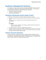
Intel Desktop Board DG965WH Product Guide RJ-45 LAN Connector LEDs Two LEDs are built into the RJ-45 LAN connector located on the back panel (see Figure 2). These LEDs indicate the status of the LAN. Figure 2. LAN Connector LEDs Table 3 describes the LED states when the board is powered up and the LAN subsystem is operating. Table 3. LAN Connector LED States LED A B LED Color Green N/A Green Yellow LED State Off On Blinking Off On On Indicates LAN link is not established LAN link is established LAN activity is occurring 10 Mb/s data rate 100 Mb/s data rate 1000 Mb/s data rate 18
-
 1
1 -
2
-
3
-
4
-
5
-
6
-
7
-
8
-
9
-
10
-
11
-
12
-
 13
13 -
 14
14 -
 15
15 -
 16
16 -
 17
17 -
 18
18 -
 19
19 -
 20
20 -
 21
21 -
 22
22 -
 23
23 -
24
-
25
-
26
-
27
-
28
-
29
-
30
-
31
-
32
-
33
-
34
-
35
-
36
-
37
-
38
-
39
-
40
-
41
-
42
-
43
-
44
-
45
-
46
-
47
-
48
-
49
-
50
-
51
-
52
-
53
-
54
-
55
-
56
-
57
-
58
-
59
-
60
-
61
-
62
-
63
-
64
-
65
-
66
-
67
-
68
-
69
-
70
-
71
-
72
-
73
-
74
-
75
-
76
-
77
-
78
-
79
-
80
-
81
-
82
-
83
-
84
 |
 |
Intel Desktop Board DG965WH Product Guide
18
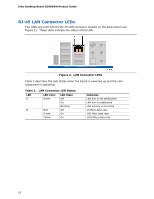
RJ-45 LAN Connector LEDs
Two LEDs are built into the RJ-45 LAN connector located on the back panel (see
Figure 2).
These LEDs indicate the status of the LAN.
Figure 2.
LAN Connector LEDs
Table 3 describes the LED states when the board is powered up and the LAN
subsystem is operating.
Table 3. LAN Connector LED States
LED
LED Color
LED State
Indicates
A
Off
LAN link is not established
Green
On
LAN link is established
Blinking
LAN activity is occurring
N/A
Off
10 Mb/s data rate
Green
On
100 Mb/s data rate
B
Yellow
On
1000 Mb/s data rate