Intel DG965WH Product Guide - Page 22
Power Management Features, ACPI, Power Connectors, Fan Headers - ram
 |
View all Intel DG965WH manuals
Add to My Manuals
Save this manual to your list of manuals |
Page 22 highlights
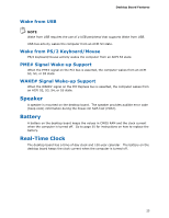
Intel Desktop Board DG965WH Product Guide Power Management Features Power management is implemented at several levels, including: • Software support through the Advanced Configuration and Power Interface (ACPI) • Hardware support: ― Power connectors ― Fan headers ― LAN wake capabilities ― Instantly Available PC technology (Suspend to RAM) ― +5 V standby power indicator LED ― Resume on Ring ― Wake from USB ― Wake from PS/2 keyboard/mouse ― Power Management Event signal (PME#) wakeup support ― WAKE# signal wake-up support ACPI ACPI gives the operating system direct control over the power management and Plug and Play functions of a computer. The use of ACPI with the desktop board requires an operating system that provides full ACPI support. Power Connectors ATX12V-compliant power supplies can turn off the computer power through system control. When an ACPI-enabled computer receives the correct command, the power supply removes all non-standby voltages. When resuming from an AC power failure, the computer returns to the power state it was in before power was interrupted (either on or off). The computer's response can be set by using the Last Power State feature in the BIOS Setup program's Boot menu. The desktop board has two power connectors. See Figure 25 on page 50 for the location of the power connectors. Fan Headers The function/operation of the fans is as follows: • The fans are on when the computer is in the ACPI S0 state. • The fans are off when the computer is in the ACPI S3, S4, or S5 state. • Each fan header is wired to a tachometer input of the hardware monitoring and control device • All fan headers support closed-loop fan control that can adjust the fan speed or switch the fan on or off as needed. • All fan headers have a +12 V dc connection. The desktop board has a 4-pin processor fan header, two 3-pin chassis fan headers, and one 4-pin chassis fan header. 22
-
 1
1 -
2
-
3
-
4
-
5
-
6
-
7
-
8
-
9
-
10
-
11
-
12
-
13
-
14
-
15
-
16
-
 17
17 -
 18
18 -
 19
19 -
 20
20 -
 21
21 -
 22
22 -
 23
23 -
 24
24 -
 25
25 -
 26
26 -
 27
27 -
28
-
29
-
30
-
31
-
32
-
33
-
34
-
35
-
36
-
37
-
38
-
39
-
40
-
41
-
42
-
43
-
44
-
45
-
46
-
47
-
48
-
49
-
50
-
51
-
52
-
53
-
54
-
55
-
56
-
57
-
58
-
59
-
60
-
61
-
62
-
63
-
64
-
65
-
66
-
67
-
68
-
69
-
70
-
71
-
72
-
73
-
74
-
75
-
76
-
77
-
78
-
79
-
80
-
81
-
82
-
83
-
84
 |
 |
