Intel DG965WH Product Guide - Page 47
Connecting to the Alternate Front Panel Power LED Header, Connecting to the IEEE 1394a Header
 |
View all Intel DG965WH manuals
Add to My Manuals
Save this manual to your list of manuals |
Page 47 highlights
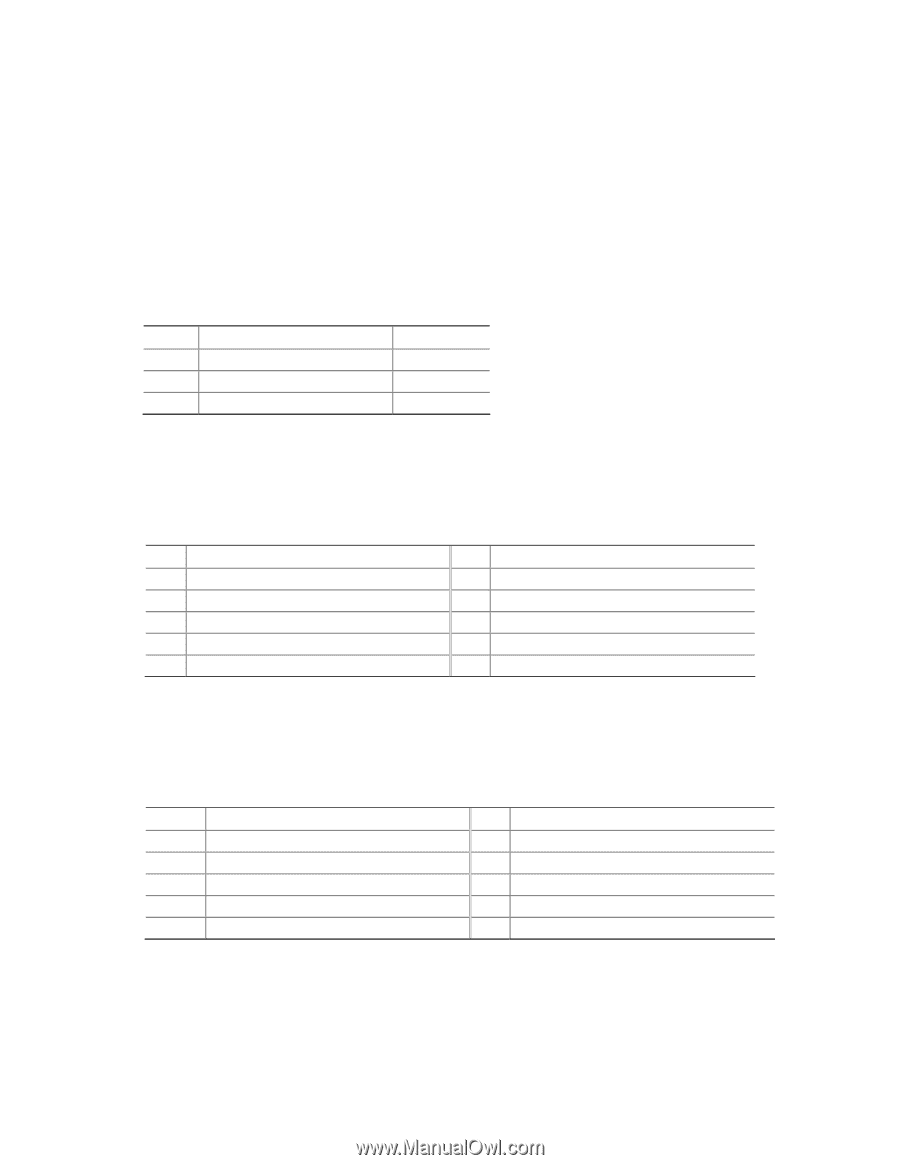
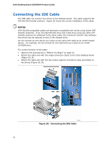
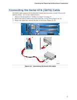
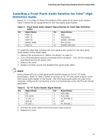
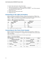
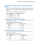
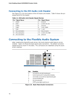
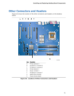
Installing and Replacing Desktop Board Components Connecting to the Alternate Front Panel Power LED Header Figure 22, F on page 44 shows the location of the alternate front panel power LED header. Pins 1 and 3 of this header duplicate the signals on pins 2 and 4 of the front panel header. If your chassis has a three-pin power LED cable, connect it to this header. Table 8 shows the pin assignments for the front panel header. Table 8. Alternate Front Panel Power LED Header Pin Description 1 Front panel green LED 2 No pin 3 Front panel yellow LED In/Out Out Out Connecting to the IEEE 1394a Header See Figure 22, B for the location of the blue IEEE 1394a header. Table 9 shows the pin assignments for the header. Table 9. IEEE 1394a Header Signal Names Pin Signal Name 1 TPA1+ 3 Ground 5 TPA2+ 7 +12 V 9 Key (no pin) Pin Signal Name 2 TPA14 Ground 6 TPA28 +12 V 10 Ground Connecting to the Serial Port Header See Figure 22, D for the location of the serial port header. Table 9 shows the pin assignments for the header. Table 10. Serial Port Header Signal Names Pin Signal Name 1 DCD Pin Signal Name 2 RXD# 3 TXD# 5 Ground 7 RTS 4 DTR 6 DSR 8 CTS 9 RI 10 No connection 47
-
 1
1 -
2
-
3
-
4
-
5
-
6
-
7
-
8
-
9
-
10
-
11
-
12
-
13
-
14
-
15
-
16
-
17
-
18
-
19
-
20
-
21
-
22
-
23
-
24
-
25
-
26
-
27
-
28
-
29
-
30
-
31
-
32
-
33
-
34
-
35
-
36
-
37
-
38
-
39
-
40
-
41
-
 42
42 -
 43
43 -
 44
44 -
 45
45 -
 46
46 -
 47
47 -
 48
48 -
 49
49 -
 50
50 -
 51
51 -
 52
52 -
53
-
54
-
55
-
56
-
57
-
58
-
59
-
60
-
61
-
62
-
63
-
64
-
65
-
66
-
67
-
68
-
69
-
70
-
71
-
72
-
73
-
74
-
75
-
76
-
77
-
78
-
79
-
80
-
81
-
82
-
83
-
84
 |
 |