Intel DQ35JO Product Guide
Intel DQ35JO - Desktop Board Executive Series Motherboard Manual
 |
UPC - 735858192194
View all Intel DQ35JO manuals
Add to My Manuals
Save this manual to your list of manuals |
Intel DQ35JO manual content summary:
- Intel DQ35JO | Product Guide - Page 1
Intel® Desktop Board DQ35JO Product Guide Order Number: D90037-004 - Intel DQ35JO | Product Guide - Page 2
Revision History First release of the Intel® Desktop Board DQ35JO Product Guide Second release of the Intel® Desktop Board DQ35JO Product Guide Third release of the Intel® Desktop Board DQ35JO Product Guide Fourth release of the Intel® Desktop Board DQ35JO Product Guide Date May 2007 January 2008 - Intel DQ35JO | Product Guide - Page 3
Preface This Product Guide gives information about board layout, component installation, BIOS update, and regulatory requirements for Intel® Desktop Board DQ35JO. Intended Audience The Product Guide is intended for technically qualified personnel. It is not intended for general audiences. Use Only - Intel DQ35JO | Product Guide - Page 4
Intel Desktop Board DQ35JO Product Guide NOTE Notes call attention to important information. Terminology The table below gives descriptions of some common terms used in the product guide. Term Description GB Gigabyte (1,073,741,824 bytes) GHz Gigahertz (one billion hertz) KB Kilobyte ( - Intel DQ35JO | Product Guide - Page 5
Supported Operating Systems 11 Desktop Board Components 12 Processor ...14 Main Memory...14 Intel® Q35 Express Chipset 15 Intel Q35 Graphics Subsystem 16 Intel® GMA 3100 Graphics Controller 16 Digital Video Interface (DVI 17 Audio Subsystem 17 Legacy Input/Output (I/O) Controller 18 LAN - Intel DQ35JO | Product Guide - Page 6
Intel Desktop Board DQ35JO Product Guide 2 Installing and Replacing Desktop Board Components Before You Begin 31 Installation Precautions 32 Prevent Power Supply Overload 32 Observe Safety and Regulatory Requirements 32 Installing the I/O Shield 33 Installing and Removing the Desktop Board 34 - Intel DQ35JO | Product Guide - Page 7
84 Product Certifications 85 Board-Level Certification Markings 85 Chassis and Component Certifications 86 Figures 1. Desktop Board DQ35JO Components 12 2. LAN Connector LEDs 19 3. Intel AMT Status Indicator 20 4. Standby Power Indicator 28 5. Installing the I/O Shield 33 6. Desktop Board - Intel DQ35JO | Product Guide - Page 8
Summary 9 2. Desktop Board DQ35JO Components 13 3. DVI Port Status 17 4. LAN Connector LEDs 19 5. Intel AMT Status Indicator 20 6. HD Audio Link Header Signal Names 51 7. IEEE 1394a Signal Header Names 51 8. Front Panel Intel High Definition Audio Header Signal Names 51 9. Serial Port Header - Intel DQ35JO | Product Guide - Page 9
Desktop Board. Table 1. Feature Summary Form Factor Processor Main Memory Chipset Graphics Audio LAN Support Expansion Capabilities Legacy I/O Support Peripheral Interfaces microATX (243.84 millimeters [9.60 inches] x 243.84 millimeters [9.60 inches]) Support for an Intel® processor in the LGA775 - Intel DQ35JO | Product Guide - Page 10
Interface (ACPI) • Suspend to RAM (STR) • Wake on USB, PCI Express, LAN, and front panel • ENERGY STAR* capable Hardware Management Intel® Active Management Technology (Intel® AMT) Hardware monitor with: • Intel® Quiet System Technology fan speed control • Three fan sensing inputs used to monitor - Intel DQ35JO | Product Guide - Page 11
Desktop Board Features Supported Operating Systems The Desktop Board supports the following operating systems: • Microsoft Windows Vista* Ultimate • Microsoft Windows Vista Enterprise • Microsoft Windows Vista Business • Microsoft Windows Vista Home Premium • Microsoft Windows Vista Home Basic • - Intel DQ35JO | Product Guide - Page 12
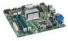
Intel Desktop Board DQ35JO Product Guide Desktop Board Components Figure 1 shows the approximate location of the major components on Desktop Board DQ35JO. Figure 1. Desktop Board DQ35JO Components 12 - Intel DQ35JO | Product Guide - Page 13
Front panel audio header Speaker PCI bus connector PCI Express x1 connector 2 Battery PCI Express x1 connector 1 PCI Express x16 connector Rear chassis fan header (3-pin) Back panel connectors 12 V processor core voltage connector (2 x 2 pin) Processor socket Processor fan header (4-pin) Serial - Intel DQ35JO | Product Guide - Page 14
more information about: • Instructions on installing or upgrading the processor, page 35 in Chapter 2 • Supported processors for Desktop Board DQ35JO, http://www.intel.com/go/findCPU Main Memory NOTE To be fully compliant with all applicable Intel ® SDRAM memory specifications, the board should be - Intel DQ35JO | Product Guide - Page 15
com/products/motherboard/index.htm?iid=HMPAGE+Header_2_Pr oduct_MB • PC Serial Presence Detect Specification, http://www.intel.com/technology/memory/ddr/specs/dda8c16_32x64ag_a.pdf Intel® Q35 Express Chipset The Intel Q35 Express Chipset consists of the following devices: • Intel Q35 Express Chipset - Intel DQ35JO | Product Guide - Page 16
Intel Desktop Board DQ35JO Product Guide Intel Q35 Graphics Subsystem The Intel Q35 Express Chipset contains two separate, mutually exclusive graphics options. Either the integrated Intel® Graphics Media Accelerator 3100 (Intel® GMA 3100) graphics controller is used or a PCI Express x16 add-in card - Intel DQ35JO | Product Guide - Page 17
stereo audio playback from back panel connectors and the Intel High Definition Audio front panel header Related Links: Go to the following link or pages for more information about: • Audio drivers and utilities http://support.intel.com/support/motherboards/desktop/ • Installing the front panel audio - Intel DQ35JO | Product Guide - Page 18
Intel Desktop Board DQ35JO Product Guide Legacy Input/Output (I/O) Controller The I/O controller features the following: • One serial port interface via an onboard header • Low pin count (LPC) interface • Serial IRQ interface compatible with serialized IRQ support for PCI systems • Intelligent power - Intel DQ35JO | Product Guide - Page 19
Desktop Board Features RJ-45 LAN Connector LEDs Two LEDs are built into the RJ-45 LAN connector located on the back panel (see Figure 2). These LEDs indicate the status of the LAN. Figure 2. LAN Connector LEDs Table 4 describes the LED states when the board is powered up and the LAN subsystem is - Intel DQ35JO | Product Guide - Page 20
Board DQ35JO Product Guide The Intel AMT subsystem consists of: • ARC4 microcontroller embedded in the Intel Q35 Graphics and Memory Controller Hub (GMCH) • ICH9DO (Intel® Management Engine function) • Intel 82566DM Gigabit (10/100/1000 Mb/s) Ethernet LAN controller • Channel A DIMM(s) • BIOS - Intel DQ35JO | Product Guide - Page 21
Desktop Board Features Hi-Speed USB 2.0 Support The Desktop Board supports up to 12 USB 2.0 ports (six ports routed to the back panel and six ports routed to three internal headers) via ICH9DO. USB 2.0 ports are backward compatible with USB 1.1 devices. USB 1.1 devices will function normally at USB - Intel DQ35JO | Product Guide - Page 22
bus connector BIOS The BIOS provides the Power-On Self-Test (POST), the BIOS Setup program, the PCI/PCI Express and IDE auto-configuration utilities, and the video BIOS. The BIOS is stored in the Serial Peripheral Interface (SPI) Flash. The BIOS can be updated by following the instructions on page - Intel DQ35JO | Product Guide - Page 23
disk drive password. NOTE The BIOS hard disk drive password security feature can only be used on ATA hard disks that support the ATA Security Mode feature set. It supports Serial ATA hard disk drives in IDE, AHCI, and RAID modes. For instructions on resetting the password, see Clearing or Changing - Intel DQ35JO | Product Guide - Page 24
Intel Desktop Board DQ35JO Product Guide Hard Disk Drive Password Feature During BIOS POST During every BIOS POST execution, if a User hard disk drive password is present on the hard drive, POST execution will pause to prompt the user to enter the Master or User password: Enter Hard Disk Drive - Intel DQ35JO | Product Guide - Page 25
System Technology fan speed control, delivering acoustically-optimized thermal management NOTE Memory must be installed in the Channel A, DIMM 0 socket to enable Intel Quiet System Technology. • Fan speed controllers and sensors integrated into the ICH9DO • Thermal sensors in the processor, GMCH - Intel DQ35JO | Product Guide - Page 26
Intel Desktop Board DQ35JO Product Guide ACPI ACPI gives the operating system direct control over the power management and Plug and Play functions of a computer. The use of ACPI with the Desktop Board requires an operating system that provides full ACPI support. Hardware Support Power Connectors - Intel DQ35JO | Product Guide - Page 27
ways: • The PCI Express WAKE# signal • The PCI bus PME# signal for PCI 2.3 compliant LAN designs • By Ping • Magic Packet • The onboard LAN subsystem Desktop Board DQ35JO supports waking the Intel Management Engine over the network. This can be enabled in the BIOS and allows Intel AMT to be remotely - Intel DQ35JO | Product Guide - Page 28
Intel Desktop Board DQ35JO Product Guide The Desktop Board supports the PCI Bus Power Management Interface Specification. Add-in cards that support this specification can participate in power management and can be used to wake the computer. +5 V Standby Power Indicator CAUTION If the AC power has - Intel DQ35JO | Product Guide - Page 29
is mounted on the Desktop Board. The speaker provides audible error code (beep code) information during the Power-On Self-Test (POST). Battery A battery on the Desktop Board keeps the values in CMOS RAM and the clock current when the computer is turned off. Go to page 59 for instructions on how to - Intel DQ35JO | Product Guide - Page 30
Intel Desktop Board DQ35JO Product Guide 30 - Intel DQ35JO | Product Guide - Page 31
shield • Install and remove the Desktop Board • Install and remove a processor • Install and remove memory • Install and remove a PCI Express x16 card • Connect the IDE and Serial ATA cables • Install the External SATA (eSATA) adapter bracket • Connect to the internal headers • Connect to the audio - Intel DQ35JO | Product Guide - Page 32
Intel Desktop Board DQ35JO Product Guide Installation Precautions When you install and test the Intel Desktop Board, observe all warnings and cautions in the installation instructions. To avoid injury, be careful of: • Sharp pins on connectors • Sharp pins on printed circuit assemblies • Rough edges - Intel DQ35JO | Product Guide - Page 33
components from dust and foreign objects, and promotes correct airflow within the chassis. Install the I/O shield before installing the Desktop Board in the chassis. Place the shield inside the chassis as shown in Figure 5. Press the shield into place so that it fits tightly and securely. If the - Intel DQ35JO | Product Guide - Page 34
Intel Desktop Board DQ35JO Product Guide Installing and Removing the Desktop Board CAUTION Only qualified technical manual for instructions on installing and removing the Desktop Board. Figure 6 shows the location of the mounting screw holes for Desktop Board DQ35JO. Figure 6. Desktop Board DQ35JO - Intel DQ35JO | Product Guide - Page 35
Installing and Replacing Desktop Board Components Installing and Removing a Processor Instructions on how to install the processor to the Desktop Board are given below. Installing a Processor CAUTION Before installing or removing the processor, make sure the AC power has been removed by unplugging - Intel DQ35JO | Product Guide - Page 36
Intel Desktop Board DQ35JO Product Guide 3. Lift the load plate (Figure 8, A). Do not touch the socket contacts (Figure 8, B). Figure 8. Lift the Load Plate 4. Remove the plastic protective socket cover from the load plate (Figure 9). Do not discard the protective socket cover. Always replace the - Intel DQ35JO | Product Guide - Page 37
and Replacing Desktop Board Components 5. Remove the processor from the protective processor cover. Hold the processor only at the edges, being careful not to touch the bottom of the processor (see Figure 10). Do not discard the protective processor cover. Always replace the processor cover if - Intel DQ35JO | Product Guide - Page 38
Intel Desktop Board DQ35JO Product Guide 7. Pressing down on the load plate (Figure 12, A), close and engage the socket lever (Figure 12, B). Figure 12. Close the Load Plate Installing the Processor Fan Heat Sink Desktop Board DQ35JO has mounting holes for a processor fan heat sink. For instructions - Intel DQ35JO | Product Guide - Page 39
Installing and Replacing Desktop Board Components Connecting the Processor Fan Heat Sink Cable Connect the processor fan heat sink cable to the 4-pin processor fan header (see Figure 13). A fan with a 4-pin connector as shown in Figure 13, A is recommended; however, a fan with a 3-pin connector ( - Intel DQ35JO | Product Guide - Page 40
Intel Desktop Board DQ35JO Product Guide Removing the Processor For instructions on how to remove the processor fan heat sink and processor, refer to the processor installation manual. Installing and Removing Memory NOTE To be fully compliant with all applicable Intel SDRAM memory specifications, - Intel DQ35JO | Product Guide - Page 41
Desktop Board Components If additional memory is to be used, install another matched pair of DIMMs in DIMM 1 (black) in channels A and B (see Figure 15). Figure 15. Dual Channel Memory equal in speed and size in DIMM 0 (blue) and DIMM 1 (black) of channel A. Install a DIMM equal in speed and total - Intel DQ35JO | Product Guide - Page 42
Intel Desktop Board DQ35JO Product Guide Installing DIMMs To make sure you have the correct DIMM, place it on the illustration of the DDR2 DIMM in Figure 17. All the notches should match with the DDR2 DIMM. Figure 17. Use DDR2 DIMMs 42 - Intel DQ35JO | Product Guide - Page 43
Installing and Replacing Desktop Board Components NOTE Memory must be installed in the Channel A, DIMM 0 socket to enable Intel Quiet System Technology. To install a DIMM, follow these steps: 1. Observe the precautions in "Before You Begin" on page 31. 2. Turn off all peripheral devices connected - Intel DQ35JO | Product Guide - Page 44
Intel Desktop Board DQ35JO Product Guide 7. Insert the bottom edge of the DIMM into the socket. 8. When the DIMM is inserted, push down on the top edge of the DIMM until - Intel DQ35JO | Product Guide - Page 45
Desktop Board Components Installing and Removing a PCI Express x16 Card CAUTION When installing a PCI Express x16 card on the Desktop Board, ensure that the card is fully seated in the PCI Express x16 connector before you power on the system. If the card is not fully seated in the PCI Express - Intel DQ35JO | Product Guide - Page 46
Intel Desktop Board DQ35JO Product Guide Removing the PCI Express x16 Card Follow these instructions to remove the PCI Express x16 card from the connector: 1. Observe the precautions in "Before You Begin" on page 31. 2. Remove the screw (Figure 20, A) that secures the card's metal bracket to the - Intel DQ35JO | Product Guide - Page 47
be used to connect two IDE drives to the Desktop Board. The cable supports the ATA-66/100 transfer protocol. Figure 21 shows on page 31. • Attach the cable end with the single connector (blue) to the Intel Desktop Board (Figure 21, A). • Attach the cable end with the two closely spaced connectors ( - Intel DQ35JO | Product Guide - Page 48
Intel Desktop Board DQ35JO Product Guide Connecting the Serial ATA (SATA) Cables SATA cables support the Serial ATA protocol. Each cable can be used to connect a single internal SATA drive to the Desktop Board. For correct cable function: 1. Observe the precaution in "Before You Begin" on page 31. - Intel DQ35JO | Product Guide - Page 49
to the red SATA connector (Figure 23, B) on the Desktop Board. 3. Secure the bracket to the chassis back panel with a screw (Figure 23, A). NOTE Do not use the red external SATA (eSATA) connector to connect to an internal SATA drive. Figure 23. Connecting the External Serial ATA Adapter Bracket 49 - Intel DQ35JO | Product Guide - Page 50
Intel Desktop Board DQ35JO Product Guide Connecting to the Internal Headers Before connecting cables to the internal headers, observe the precautions in "Before You Begin" on page 31. Figure 24 shows the location of the internal headers. Item Description A HD Audio Link B Front Panel Audio C - Intel DQ35JO | Product Guide - Page 51
, B shows the location of the front panel audio header. Table 8 shows the pin assignments for the front panel audio header. Table 8. Front Panel Intel High Definition Audio Header Signal Names Pin Signal Name 1 PORT 1L 3 PORT 1R 5 PORT 2R 7 SENSE_SEND 9 PORT 2L Pin Signal Name 2 GND - Intel DQ35JO | Product Guide - Page 52
Intel Desktop Board DQ35JO Product Guide To install the cable that connects the front panel audio solution to the front panel audio header, follow these steps: 1. Observe the precautions in "Before You Begin" on page 31. 2. Turn off all peripheral devices connected to the computer. Turn off - Intel DQ35JO | Product Guide - Page 53
Installing and Replacing Desktop Board Components Connecting to the Alternate Front Panel Power LED Header Figure 24, F on page 50 shows the location of the alternate front panel power LED header. Pins 1 and 3 of this header duplicate the signals on pins 2 and 4 of the front panel header. If your - Intel DQ35JO | Product Guide - Page 54
cable. Use a shielded cable that meets the requirements for a full-speed USB device. Connecting to the Audio System After installing the RealTek audio driver from the Intel Express Installer DVD-ROM, the multi-channel audio feature can be enabled. Figure 25 shows the back panel audio connectors. The - Intel DQ35JO | Product Guide - Page 55
Installing and Replacing Desktop Board Components NOTE The back panel audio line out connector is designed to power either headphones or amplified speakers only. Poor audio quality may occur if passive (non-amplified) speakers are connected to this output. Connecting Chassis Fan and Power Supply - Intel DQ35JO | Product Guide - Page 56
Intel Desktop Board DQ35JO Product Guide Connecting Supply Power Cables CAUTION Failure to use an appropriate power supply and/or not connecting the 12 V (2 x 2 pin) power connector to the Desktop Board may result in damage to the board or the system may not function properly. The 2 x 12 pin main - Intel DQ35JO | Product Guide - Page 57
computer operation. Figure 28 shows the location of the Desktop Board's BIOS configuration jumper block. Figure 28. Location of the BIOS Configuration Jumper Block The three-pin BIOS jumper block enables all board configuration to be done in the BIOS Setup program. Table 14 shows the jumper settings - Intel DQ35JO | Product Guide - Page 58
Intel Desktop Board DQ35JO Product Guide Table 14. Jumper Settings for the BIOS Setup Program Modes Jumper Setting Mode Normal (default) (1-2) Description The BIOS uses the current configuration and passwords for booting. Configure (2-3) After the Power-On Self-Test (POST) runs, the BIOS - Intel DQ35JO | Product Guide - Page 59
Installing and Replacing Desktop Board Components 6. Replace the cover, plug in the computer, turn delete the password, the user must first enter the existing User hard disk drive password in BIOS Setup for security confirmation. To delete an existing User hard disk drive password, the user can - Intel DQ35JO | Product Guide - Page 60
Intel Desktop Board DQ35JO Product Guide Replacing the Battery A coin-cell battery (CR2032) powers the real-time clock and CMOS memory. VSB applied. When the voltage drops below a certain level, the BIOS Setup program settings stored in CMOS RAM (for example, the date and time) might not be accurate. - Intel DQ35JO | Product Guide - Page 61
Installing and Replacing Desktop Board Components VORSICHT Bei falschem Einsetzen einer neuen Batterie besteht Explosionsgefahr. Die Batterie darf nur durch denselben oder einen entsprechenden, vom Hersteller empfohlenen Batterietyp ersetzt werden. - Intel DQ35JO | Product Guide - Page 62
Intel Desktop Board DQ35JO Product Guide VIGYAZAT Ha a telepet nem a megfelelő típusú telepre cseréli, az felrobbanhat. A telepeket lehetőség szerint újra kell hasznosítani. A használt telepeket a helyi környezetvédelmi előírá - Intel DQ35JO | Product Guide - Page 63
Installing and Replacing Desktop Board Components . UYARI Yanlış türde pil takıldığında patlama riski vardır. Piller mümkün olduğunda geri dönüştürülmelidir. Kullanılmış piller, yerel çevre yasalarına uygun olarak atılmalıdır. O 63 - Intel DQ35JO | Product Guide - Page 64
Intel Desktop Board DQ35JO Product Guide To replace the battery, follow these steps: 1. Observe the source (wall outlet or power adapter). 3. Remove the computer cover. 4. Locate the battery on the board (see Figure 29). 5. With a medium flat-bladed screwdriver, gently pry the battery free from its - Intel DQ35JO | Product Guide - Page 65
of the Intel® Flash Memory Update Utility and the ease of use of Windows-based installation wizards. To update the BIOS with the Intel Express BIOS Update utility: 1. Go to the Intel World Wide Web site: http://support.intel.com/support/motherboards/desktop/ 2. Navigate to the DQ35JO page, click - Intel DQ35JO | Product Guide - Page 66
Intel Desktop Board DQ35JO Product Guide Updating the BIOS with the ISO Image BIOS Update File or the Iflash Memory Update Utility You can use the information in this section to update the BIOS using either the Iflash Memory Update Utility or the ISO Image BIOS update file. Obtaining the BIOS Update - Intel DQ35JO | Product Guide - Page 67
Intel Desktop Board BIOS Upgrade CD-ROM" page, press any key to confirm the BIOS upgrade operation. 6. Wait for the BIOS upgrade process to complete. CAUTION DO NOT POWER DOWN YOUR COMPUTER before the update is complete. The update may take up to 5 minutes. Updating the BIOS with the Iflash Memory - Intel DQ35JO | Product Guide - Page 68
Intel Desktop Board DQ35JO Product Guide CAUTION Do not interrupt the process or the system may not function properly. 1. Uncompress the BIOS update file and copy the .BIO file, IFLASH.EXE, and .ITK file (optional) to a bootable USB flash drive or other bootable USB media. 2. Configure the BIOS or - Intel DQ35JO | Product Guide - Page 69
Windows XP operating system and SATA hard drives. Configuring the BIOS for Intel Matrix Storage Technology 1. Assemble your system and attach one or more SATA hard drives to the SATA connectors. 2. Enter system BIOS Setup by pressing the key after the Power-On-Self-Test (POST) memory RAID array - Intel DQ35JO | Product Guide - Page 70
the Windows installation and install all necessary drivers. 4. Install the Intel Matrix Storage Console software via the Intel Express Installer CD/DVD included with your desktop board or after downloading it from the Internet at http://support.intel.com/support/motherboards/desktop/. The Intel - Intel DQ35JO | Product Guide - Page 71
previously not set to RAID and you already have an operating system installed, you must reinstall it. Follow the instructions in Chapter 5 to install the Intel Matrix Storage RAID driver during the operating system installation. 5. Exit and save settings. Proceed to "Creating a Recovery Volume." 71 - Intel DQ35JO | Product Guide - Page 72
Intel Desktop Board DQ35JO Product Guide Creating a Recovery Volume A recovery volume consists of two disks - a master disk and a recovery disk. A recovery volume can be created with either the RAID Option ROM (OROM) or the Intel® Matrix Storage Console application. Creating a Recovery Volume Using - Intel DQ35JO | Product Guide - Page 73
volume. Disk Synchronization Mode There are two modes of updating or synchronizing the recovery disk with the master disk - either continuous update or manual update. To change from Continuous Update mode to Update On Request mode using the Intel Matrix Storage Console, select the Advanced mode from - Intel DQ35JO | Product Guide - Page 74
Intel Desktop Board DQ35JO Product Guide To un-mount the recovery disk, complete the following steps: 1. In the Advanced mode, right-click on the recovery volume name. 2. Select Access Recovery Drive Files. 3. Select OK on the information dialog box. The recovery disk is now un-mounted and reappears - Intel DQ35JO | Product Guide - Page 75
Desktop Board DQ35JO reports POST errors in two ways: • By sounding a beep code • By displaying an error message on the monitor BIOS Beep Codes The BIOS also issues a beep code (one long tone followed by two short tones) during POST if the video configuration fails (a faulty video card or no card - Intel DQ35JO | Product Guide - Page 76
Intel Desktop Board DQ35JO Product Guide 76 - Intel DQ35JO | Product Guide - Page 77
regulatory compliance information for Desktop Board DQ35JO: • Safety standards • European Union Declaration of Conformity statement • Product Ecology statements • Electromagnetic Compatibility (EMC) regulations • Product certifications Safety Standards Desktop Board DQ35JO complies with the safety - Intel DQ35JO | Product Guide - Page 78
Intel Desktop Board DQ35JO Product Guide European Union Declaration of Conformity Statement We, Intel Corporation, declare under our sole responsibility that the product Intel® Desktop Board DQ35JO is in conformity with all applicable essential requirements necessary for CE marking, following the - Intel DQ35JO | Product Guide - Page 79
. Recycling Considerations As part of its commitment to environmental responsibility, Intel has implemented the Intel® Product Recycling Program to allow retail consumers of Intel's branded products to return used products to selected locations for proper recycling. Please consult http://www - Intel DQ35JO | Product Guide - Page 80
Intel Desktop Board DQ35JO Product Guide Deutsch Als Teil von Intels Engagement für den Umweltschutz hat das Unternehmen das Intel Produkt-Recyclingprogramm implementiert, das Einzelhandelskunden von Intel Markenprodukten ermöglicht, gebrauchte Produkte an ausgewählte Standorte für ordnungsgemäßes - Intel DQ35JO | Product Guide - Page 81
ına gidin. Lead-Free Desktop Board This Desktop Board is a European Union Restriction of Hazardous Substances (EU RoHS Directive 2002/95/EC) compliant product. EU RoHS restricts the use of six materials. One of the six restricted materials is lead. Intel Desktop Board DQ35JO is lead-free although - Intel DQ35JO | Product Guide - Page 82
Intel Desktop Board DQ35JO Product Guide Table 18 shows the lead-free board markings as they appear on the board and accompanying collateral. Table 18. Lead-Free Board Markings Description Mark Lead-Free 2nd Level Interconnect: This symbol is used to identify electrical and electronic - Intel DQ35JO | Product Guide - Page 83
Regulatory Compliance EMC Regulations Desktop Board DQ35JO complies with the EMC regulations stated in Table 19 when correctly installed in a compatible host system. Table 19. EMC Regulations Regulation FCC 47 CFR Part 15, Subpart B ICES-003 Issue 4 (Class B) EN55022:2006 (Class B) EN55024:1998 - Intel DQ35JO | Product Guide - Page 84
Intel Desktop Board DQ35JO Product Guide Korean Class B statement translation: This is household equipment that reading the installation instructions for the host chassis, power supply, and other modules: • Product certifications or lack of certifications • External I/O cable shielding and filtering - Intel DQ35JO | Product Guide - Page 85
(ACA) C-tick mark. Includes adjacent Intel supplier code number, N-232. Japan VCCI (Voluntary Control Council for Interference) mark. S. Korea MIC (Ministry of Information and Communication) mark. Includes adjacent MIC certification number: CPU-DQ35JO (B). Taiwan BSMI (Bureau of Standards - Intel DQ35JO | Product Guide - Page 86
Intel Desktop Board DQ35JO Product Guide Chassis and Component Certifications Ensure that the chassis and certain components; such as the power supply, peripheral drives, wiring, and cables; are components certified for the country or market where used. Agency certification marks on the product are
-
 1
1 -
 2
2 -
 3
3 -
 4
4 -
 5
5 -
 6
6 -
 7
7 -
8
-
9
-
10
-
11
-
12
-
13
-
14
-
15
-
16
-
17
-
18
-
19
-
20
-
21
-
22
-
23
-
24
-
25
-
26
-
27
-
28
-
29
-
30
-
31
-
32
-
33
-
34
-
35
-
36
-
37
-
38
-
39
-
40
-
41
-
42
-
43
-
44
-
45
-
46
-
47
-
48
-
49
-
50
-
51
-
52
-
53
-
54
-
55
-
56
-
57
-
58
-
59
-
60
-
61
-
62
-
63
-
64
-
65
-
66
-
67
-
68
-
69
-
70
-
71
-
72
-
73
-
74
-
75
-
76
-
77
-
78
-
79
-
80
-
81
-
82
-
83
-
84
-
85
-
86
 |
 |

Intel
®
Desktop Board DQ35JO
Product Guide
Order Number:
D90037-004