Intel VC820 Design Guide - Page 113
Post-Layout Simulation, 3.2.5.1 Intersymbol Interference, 3.2.5.2 Cross-Talk Analysis
 |
View all Intel VC820 manuals
Add to My Manuals
Save this manual to your list of manuals |
Page 113 highlights
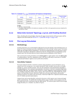
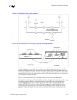
Advanced System Bus Design 3.2.5 3.2.5.1 3.2.5.2 3.2.5.3 Post-Layout Simulation Following layout, extract the interconnect information for the board from the CAD layout tools. Run simulations to verify that the layout meets timing and noise requirements. A small amount of "tuning" may be required; experience at Intel has shown that sensitivity analysis dramatically reduces the amount of tuning required. The post layout simulations should take into account the expected variation for all interconnect parameters. Intel specifies signal integrity at the device pads and therefore recommends running simulations at the device pads for signal quality. However, Intel specifies core timings at the device pins, so simulation results at the device pins should be used later to correlate simulation performance against actual system measurements. Intersymbol Interference Intersymbol Interference (ISI) refers to the distortion or change in the waveform shape caused by the voltage and transient energy on the network when the driver begins its next transition. Intersymbol Interference (ISI) occurs when transitions in the current cycle interfere with transitions in subsequent cycles. ISI can occur when the line is driven high, low, and then high in consecutive cycles (the opposite case is also valid). When the driver drives high on the first cycle and low on the second cycle, the signal may not settle to the minimum VOL before the next rising edge is driven. This results in improved flight times in the third cycle. Intel performed ISI simulations for the topology given in this section by comparing flight times for the first and third cycle. ISI effects do not necessarily span only 3 cycles so it may be necessary to simulate beyond 3 cycles for certain designs. After simulating and quantifying ISI effects, adjust the timing budget accordingly to take these conditions into consideration. Cross-Talk Analysis AGTL+ cross-talk simulations can consider the processor core package, Intel 82820 MCH package, and SC242 connectors as non-coupled. Treat the traces on the processor cartridge and baseboard as fully coupled for maximum cross-talk conditions. Simulate the traces as lossless for worst case cross-talk and lossy where more accuracy is needed. Evaluate both odd and even mode cross-talk conditions. AGTL+ Cross-talk simulation involves the following cases: • Intra-group AGTL+ cross-talk • Inter-group AGTL+ cross-talk • Non-AGTL+ to AGTL+ cross-talk Monte Carlo Analysis Perform a Monte Carlo analysis on the extracted baseboard. Vary all parameters recommended for the pre-layout Monte Carlo analysis within the region that they are expected to vary. The range for some parameters will be reduced compared to the pre-layout simulations. For example, baseboard lengths L1 through L7 should no longer vary across the full min and max range on the final baseboard design. Instead, baseboard lengths should now have an actual route, with a length tolerance specified by the baseboard fabrication manufacturer. Intel®820 Chipset Design Guide 3-13
-
 1
1 -
2
-
3
-
4
-
5
-
6
-
7
-
8
-
9
-
10
-
11
-
12
-
13
-
14
-
15
-
16
-
17
-
18
-
19
-
20
-
21
-
22
-
23
-
24
-
25
-
26
-
27
-
28
-
29
-
30
-
31
-
32
-
33
-
34
-
35
-
36
-
37
-
38
-
39
-
40
-
41
-
42
-
43
-
44
-
45
-
46
-
47
-
48
-
49
-
50
-
51
-
52
-
53
-
54
-
55
-
56
-
57
-
58
-
59
-
60
-
61
-
62
-
63
-
64
-
65
-
66
-
67
-
68
-
69
-
70
-
71
-
72
-
73
-
74
-
75
-
76
-
77
-
78
-
79
-
80
-
81
-
82
-
83
-
84
-
85
-
86
-
87
-
88
-
89
-
90
-
91
-
92
-
93
-
94
-
95
-
96
-
97
-
98
-
99
-
100
-
101
-
102
-
103
-
104
-
105
-
106
-
107
-
 108
108 -
 109
109 -
 110
110 -
 111
111 -
 112
112 -
 113
113 -
 114
114 -
 115
115 -
 116
116 -
 117
117 -
 118
118 -
119
-
120
-
121
-
122
-
123
-
124
-
125
-
126
-
127
-
128
-
129
-
130
-
131
-
132
-
133
-
134
-
135
-
136
-
137
-
138
-
139
-
140
-
141
-
142
-
143
-
144
-
145
-
146
-
147
-
148
-
149
-
150
-
151
-
152
-
153
-
154
-
155
-
156
-
157
-
158
-
159
-
160
-
161
-
162
-
163
-
164
-
165
-
166
-
167
-
168
-
169
-
170
-
171
-
172
-
173
-
174
-
175
-
176
-
177
-
178
-
179
-
180
-
181
-
182
-
183
-
184
-
185
-
186
-
187
-
188
-
189
-
190
-
191
-
192
-
193
-
194
-
195
-
196
-
197
-
198
-
199
-
200
-
201
-
202
-
203
-
204
-
205
-
206
-
207
-
208
-
209
-
210
-
211
-
212
-
213
-
214
-
215
-
216
-
217
-
218
-
219
-
220
-
221
-
222
-
223
-
224
-
225
-
226
-
227
-
228
-
229
-
230
-
231
-
232
-
233
-
234
-
235
-
236
-
237
-
238
-
239
-
240
-
241
-
242
 |
 |