Invacare TRSX5 Owners Manual - Page 74
Options
 |
View all Invacare TRSX5 manuals
Add to My Manuals
Save this manual to your list of manuals |
Page 74 highlights
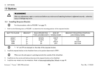
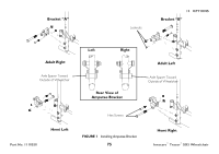
13 OPTIONS 13 Options ƽ WARNING After any adjustments, repair or service and before use, make sure all attaching hardware is tightened securely - otherwise injury or damage may occur. 13.1 Installing Amputee Bracket For ths procedure, refer to FIGURE 1 on page 75. 1. Refer to the following chart or FIGURE 1 to determine the mounting position of the amputee bracket: SEAT-TO-FLOOR ADULT ADULT HEMI HEMI BRACKET A* B* B* A* AXLE SPACER POSI- SIDE OF TION (ON BRACKET) WHEELCHAIR DOWN DOWN UP UP RIGHT LEFT RIGHT LEFT * - "A" and "B" are stamped on the sides of the amputee bracket. 2. Install the amputee bracket on the wheelchair frame to the position determined in STEP 1. BRACKET MOUNTING POSITION (ON WHEELCHAIR) TOP TOP BOTTOM BOTTOM Make sure the axle spacer is pointing towards the outside of the wheelchair. 3. Install the two hex screws and locknuts that secure the amputee bracket to the wheelchair. 4. Install the rear wheels onto the wheelchair. Refer to Removing/Installing Rear Wheels on page 49. Invacare® Tracer® SX5 Wheelchair 74 Part No. 1110550
-
 1
1 -
2
-
3
-
4
-
5
-
6
-
7
-
8
-
9
-
10
-
11
-
12
-
13
-
14
-
15
-
16
-
17
-
18
-
19
-
20
-
21
-
22
-
23
-
24
-
25
-
26
-
27
-
28
-
29
-
30
-
31
-
32
-
33
-
34
-
35
-
36
-
37
-
38
-
39
-
40
-
41
-
42
-
43
-
44
-
45
-
46
-
47
-
48
-
49
-
50
-
51
-
52
-
53
-
54
-
55
-
56
-
57
-
58
-
59
-
60
-
61
-
62
-
63
-
64
-
65
-
66
-
67
-
68
-
 69
69 -
 70
70 -
 71
71 -
 72
72 -
 73
73 -
 74
74 -
 75
75 -
 76
76 -
 77
77 -
 78
78 -
 79
79 -
80
 |
 |
