JVC C11U Instruction Manual
JVC C11U - VN Network Camera Manual
 |
UPC - 046838325670
View all JVC C11U manuals
Add to My Manuals
Save this manual to your list of manuals |
JVC C11U manual content summary:
- JVC C11U | Instruction Manual - Page 1
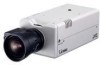
V.NETWORKS Model VN-C11 INSTRUCTIONS For Customer Use: Enter below the Serial No. which is located on the body. Retain this information for future reference. Model No. VN-C11 Serial No. LWT0126-001A - JVC C11U | Instruction Manual - Page 2
will be abused by persons walking on it. 13. Follow all warnings and instructions marked on the appliance. 14. Do not overload wall outlets and extension cords a need for service. 18. When replacement parts are required, be sure the service technician has used replacement parts specified by the - JVC C11U | Instruction Manual - Page 3
servicing) instructions in the literature accompanying the appliance. Information for USA This device complies with part 15 of the FCC Rules. Changes or modifications not approved by JVC installed and used in accordance with the instruction manual, may cause harmful interference to radio - JVC C11U | Instruction Manual - Page 4
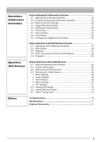
. (These instructions are for VN-C11U.) Before beginning to operate this unit, please read the instruction manual carefully in order 15 1-4 Connecting the Alarm I/O Terminals 16 1-5 Installing the Camera 18 Step 2 Setting the Network 2-1 Installing the Software 19 2-2 Setting the PC's IP Address - JVC C11U | Instruction Manual - Page 5
Operations with V.Networks Controller 5-1 Operations with V.Networks Controller 55 5-2 Record/Stop 56 5-3 Playback 57 5-4 Other Instructions on Record Still Images 73 6-6 Viewing Moving Images 74 6-7 VN-C11 Image Link 75 Others Troubleshooting 76 Specifications 77 External Dimensions 77 5 - JVC C11U | Instruction Manual - Page 6
peripheral equipment for such cameras to be also used for VN-C11. • With a built-in Web server, VN-C11 supports Internet Explorer and Netscape. • Multicast function. (Only for JPEG) Items Included CD-ROM (The Instruction Manual inside) Read Me First Warranty Card Service Information Card How to - JVC C11U | Instruction Manual - Page 7
Display/Video Card : Windows 2000 (Service network connected with IEEE802.3 hubs. Note The PC specifications above are only for a reference purpose. They are not meant to guarantee a smooth operation of the application software. Depending on the usage of the PC, there may be cases where problems - JVC C11U | Instruction Manual - Page 8
Operating Precautions ● VN-C11 is designed for indoor use. For outdoor use, prepare a proper housing to cover and protect the camera. ● The product the product design, therefore not a defect. (This product uses a network protocol called RTP for transmitting MPEG4 images. Generally, an NAT router - JVC C11U | Instruction Manual - Page 9
or a pan/tilt unit. The screw length must not exceed 7 mm. If a longer screw is used, the internal parts of the camera may be damaged. MAX. 7 mm 6 Fall-preventive holes For installing the camera securely, use these holes to prevent it from falling off. 7 Screws for the bracket (x 2: M2.6 X 6 mm - JVC C11U | Instruction Manual - Page 10
becomes steady on. If the indicator blinks while the camera is in use, check the camera and/or the network equipment. & [MONITOR OUT] terminal For connecting to monitor TV when deciding camera angles. Caution For angle adjustment only, problems such as noise may occur if connected with a switcher - JVC C11U | Instruction Manual - Page 11
MAC address LAN PC Av Pk L H ALC LEVEL Network Connection VN-C11 BF LOCK MAC address Av Pk L H ALC LEVEL Av Pk L H ALC LEVEL VN-C11 BF LOCK MAC address FTP Server LAN INTERNET Av Pk L H ALC LEVEL PC Peer-to-Peer Connection VN-C11 BF LOCK MAC address Images are automatically PC - JVC C11U | Instruction Manual - Page 12
☞ page 43) ☞ Page 13 Step 2 Setting the Network Install the software [V.Networks Controller], and set the network for the PC and VN-C11. Also perform the setting with [V.Networks Setup Tool] and registration of the connected camera with [V.Networks Controller]. ☞ Page 19 ❈ If multiple PCs are in - JVC C11U | Instruction Manual - Page 13
, check the mount method of the lens. VN-C11 is set for CS-mount at the as it may cause damage to the internal parts of the camera and proper lens attachment would not be possible. 2. Attach the lens to the camera securely by turn- ing it clockwise. 3. In the case of a DC IRIS lens, connect the lens - JVC C11U | Instruction Manual - Page 14
power-supply voltage.The rated voltage for VN-C11 is DC 12 V or AC 24 V, 50 VN-C11 first and proceed the setting to 2-4 Other Settings with V.Networks Setup Tool. Only then turn on the power for a second one and go on to 2-4. Repeat the procedure for the other cameras. Note The IP address of VN - JVC C11U | Instruction Manual - Page 15
a LAN Cable Connect the camera to a hub or a PC by using a LAN cable. DC12V AC24V CLASS 2 ONLY For USA ISOLATED POWER ONLY For EUROPE INPUT OUTPUT 1 2 G 2 1 OUT COM ALARM PUSH POWER MONITOR OUT 10BASE-T/100BASE-TX For USA DO NOT CONNECT TO THE TELEPHONE NETWORK • For hub connection Use - JVC C11U | Instruction Manual - Page 16
, the camera may not work properly even if the length of the cable is less than 50 m. If this occurs, use a shielded cable or keep the cable away from the noise source. Alarm Input Terminal This terminal is for connecting with a sensor, infrared, door or metallic, or a manual switch. VN-C11 DC3 - JVC C11U | Instruction Manual - Page 17
open collector output (The output logic is set with [V.Networks Setup Tool.]) • Allowed applied voltage: DC 12 V max. • Allowed input current: 300 mA • Momentary output: 2 to 5000 ms (The duration is set with [V.Networks Setup Tool.]) Caution Connect the VN-C11 grounding terminal to the one of the - JVC C11U | Instruction Manual - Page 18
of the length of 6 mm should be used. Do not use a longer screw as it may damage the internal parts of the camera. [Fall Prevention] WARNING • Special care is required if the camera is installed on a wall or ceiling. You should not attempt to install it by yourself as it may cause injury - JVC C11U | Instruction Manual - Page 19
Tool 1. Open the [JVC] folder and then the "setup" folder inside. Select [Setup.exe]. 2. Proceed by following the instructions shown on the screen. 3. If the installation is successfully executed, the [V.Networks] icon is created in [Programs] of the Windows [Start] menu. [vn-c11u Setup Tool] is - JVC C11U | Instruction Manual - Page 20
and also if the IP address to be allotted to [V.Networks] is already known, skip 2-2 [Setting the PC's IP Address]. 1. Click . • Right-click [My Network] and select [Properties]. 2. Select the network connected to the PC by which VN-C11 is operated. • Right-click to select [Properties]. Ensure - JVC C11U | Instruction Manual - Page 21
Address] to "192.168.0.3." Note ● Before changing the IP address, note down the original address. ● Do not use the same IP address elsewhere in this network environment. Set [Subnet Mask] to an appropriate value according to the operating environment. Ask the - JVC C11U | Instruction Manual - Page 22
to set the IP address of the PC by which the camera is operated. With Windows 2000, follow the procedure below to set the IP address. 1. Click . Select [Settings] and click [Control Panel]. 2. Double-click [Network and Dial-up Co...]. 3. Double-click [Local Area Connection]. Select [Internet - JVC C11U | Instruction Manual - Page 23
the following IP Address]. Set the IP address to "192.168.0.3." Set [Subnet mask] to an appropriate value according to the operating environment. Ask the network administrator if necessary. 5. Click . 23 - JVC C11U | Instruction Manual - Page 24
the factory, DHCP is set enabled for VN-C11. ● About the DHCP function JVC does not recommend operating VN-C11 with this function enabled because a different [Programs], [V.NETWORKS] and then [vn-c11u Setup Tool] to start up [V.Networks Setup Tool]. Enter the IP address of the camera to be connected - JVC C11U | Instruction Manual - Page 25
Controller]. (☞Page 42) Note In a system where more than one VN-C11 are used, turn on the power for a VN-C11 first and proceed the setting to 2-4 Other Settings with V.Networks Setup Tool. Only then turn on the power for a second one and go on to 2-4. Repeat the procedure for the other cameras. 25 - JVC C11U | Instruction Manual - Page 26
Setup Tool Set passwords, alarm, motion detection etc. by using the installed [V.Networks Setup Tool]. 1. Select [Start], [Programs], [V.NETWORKS] and then [vn-c11u Setup Tool] to start up [V.Networks Setup Tool]. ☞Page 27 ☞Page 38 ☞Page 39 ☞Page 40 ☞Page 34 ☞Page 41 ☞Page 38 ☞Page 28 ☞Page 30 - JVC C11U | Instruction Manual - Page 27
2-4 Other Settings with V.Networks Setup Tool [1. Password Setting] VN-C11 is equipped with an access protection (security) function that, by setting passwords, regulates users of the connected PC. Setting and cancellation of passwords can be performed with [V.Networks Setup Tool]. According to - JVC C11U | Instruction Manual - Page 28
. (☞ Page 30) Operation when alarm input is activated. • Output signals are sent from the output terminal located on the rear panel of the camera, [ALARM OUTPUT]. (☞ Page 17) • Alarm information is reported to [V.Networks Controller.] (☞ Page 29) • Alarm Images are recorded. (☞ Page 32) 1. Start up - JVC C11U | Instruction Manual - Page 29
port setting. Note Note Depending on the LAN environment, alarm alert might fail. If it fails, set the value to "3". In such a case, alarm by [V.Networks Controller] itself is set off only once. 6 Alarm force output If [Output] is pressed, alarm signals are sent to the [ALARM OUTPUT] terminal. This - JVC C11U | Instruction Manual - Page 30
2 Setting the Network) 2-4 Other Settings with V.Networks Setup Tool [3. Motion Detection Setting] This section describes the setting of the motion detection function which enables VN-C11 to trigger described in this document. In no case, shall JVC be liable for any accidents and/or damage caused. 30 - JVC C11U | Instruction Manual - Page 31
Setup Tool [3. Motion Detection Setting] (continued) 3. Press [Detail] to display [Motion Detection Setting]. V.Networks General Setting Refresh Interval The reference image on which motion detection is based is refreshed at a regular interval. In a condition where the reference image changes - JVC C11U | Instruction Manual - Page 32
an alarm is activated, image recording can be carried out in one of the following two ways. One way, local recording, saves images to the VN-C11 memory, and the other records images with [V.Networks Controller] and saves them to the PC hard disc drive, etc. (☞ Page 51) 1. Start up - JVC C11U | Instruction Manual - Page 33
of local recording to the PC As local recording images are saved to the VN-C11 volatile memory, the images are deleted if the power is turned off to an FTP server. (☞ Page 34 "Rec File FTP") With recording by [V.Networks Controller], with which images are saved to the PC hard disk drive, etc., saved - JVC C11U | Instruction Manual - Page 34
Preparations (Step 2 Setting the Network) 2-4 Other Settings with V.Networks Setup Tool [5. FTP Client Setting] VN-C11 is equipped with an FTP client function which regularly uploads still images to an existing FTP server, thus enabling simultaneous image monitoring at many - JVC C11U | Instruction Manual - Page 35
2-4 Other Settings with V.Networks Setup Tool [5. FTP Client Setting] (continued) 1 FTP 9 Error Recovery To occurred for TCP connection or FTP verification of VN-C11. Retry forever : Recovery attempt is repeated until the Note power for VN-C11 is ● Uploading automatically starts when a - JVC C11U | Instruction Manual - Page 36
the same multicast address for different devices on the same system. ● To view VN-C11 images in the multicast mode through a router, an operating environment or a router setting is required as follows: 1 The router supports IGMP Ver. 2 and is synchronized with the starting and stopping of multicast - JVC C11U | Instruction Manual - Page 37
2-4 Other Settings with V.Networks Setup Tool [6. Multicast] (continued) VN-C11 multicast addresses on the network can be searched. 1. Start up [V.Networks Setup Tool]. Select [Search]. Click [Search...]. 2. The [V.Networks Search] screen is displayed. Click [Multicast search]. 3. The [Multi Address - JVC C11U | Instruction Manual - Page 38
can be selected as the image compression format. 1. Start up [V.Networks Setup Tool] and for the compression format, select JPEG or MPEG4. time. If 5 or more clients are connected, the message "The VN-C11U has not start the Streaming Service." appears. ● In the MPEG4 mode with the frame rate set to - JVC C11U | Instruction Manual - Page 39
as the default page of the web browser. 1. Start up [V.Networks Setup Tool] and select [Web]. Select whether to enable the possible to enhance the level of security by changing the default port number (80) of VN- C11 HTTP server (1 through 65535 excluding 21 and 554). With this number changed, it - JVC C11U | Instruction Manual - Page 40
client software, HTML pages, GIF and JPEG images can be uploaded. 1. Start up [V.Networks Setup Tool] and select [FTP Server]. Select whether to enable or disable the FTP Web browser. ("192.168.0.2" denotes the VN-C11 IP address when "aaa.html" is refered to.) ● Folders cannot be created in the - JVC C11U | Instruction Manual - Page 41
section describes how to set the standard time for VN-C11. NTP can be used for this function. 1. Start up [V.Networks Setup Tool] and select [Time]. There are registry backups. JVC shall not be held liable for any loss caused by registry editing. 2. Restart the Windows Time Service. This can - JVC C11U | Instruction Manual - Page 42
enter the IP address allotted by the DHCP server. Enter [V.Network Name], a name under which the camera is registered. Use a name that is easy to remember, folder here. You can set whether VN-C11 automatically starts recording upon connection. Note For connecting VN-C11 with the factory settings, - JVC C11U | Instruction Manual - Page 43
ring of the lens, adjust the back-focus as follows. 1. Loosen the back-focus lock screw by turning it counterclockwise with a Phillips screwdriver. 2. Aim the camera at the object or a spot of detail somewhere away from the object while checking the image on the PC screen. 3. Turn the focus ring to - JVC C11U | Instruction Manual - Page 44
password. • This [Controller] can be connected to VN-C1, VN-C2, VN-C3, VN-C30 (only for JPEG), VN- A1, VN-C10 and VN-C11. • In the MPEG4 mode, up to 4 clients can be connected at one time. If 5 or more clients are connected, the message "The VN-C11U has not start the Streaming Service." appears. 44 - JVC C11U | Instruction Manual - Page 45
4-2 Function Settings with V.Networks Controller With [V.Networks Controller], settings for image size, alarm etc. can be performed. 12 3 4 1 File New Delete 3 Setting : Creates a new file if Quality the camera is connected for the first time. Framerate : Deletes a file. Motion Detect Standby - JVC C11U | Instruction Manual - Page 46
Controller) 4-3 Motion Detection Standby With [V.Networks Controller] running, automatic connection will be activated upon reception of motion detection alert from VN-C11. 1. Select [File] and then [Motion Detect Standby]. 2. Select the camera. 3. Click . Select the camera for which you wish to - JVC C11U | Instruction Manual - Page 47
4-4 Image Size and Inversion With [V.Networks Controller], it is possible to set the size of mode, image details can be checked. Not suitable when a moving object is to be recorded. (only for VN-C11 firmware version 1.4 and subsequently) ● 640 x 480 size is only use in fine mode. Click . Note - JVC C11U | Instruction Manual - Page 48
Controller) 4-5 Setting the Image Quality With [V.Networks Controller], settings for image quality such as the image compression rate, white balance, etc., can be done. 1. Select [Setting] and [Quality]. 2. Change the set values. ( - JVC C11U | Instruction Manual - Page 49
light source in the background of the object, VN-C11 adjusts the weighted zone. R gain : To manually adjust the white balance toward more red intensity. turned on when AGC is set to [OFF]. ● Do not use AES with a DC IRIS lens. It may cause flickering. 6 Default Returns all values, except that for - JVC C11U | Instruction Manual - Page 50
Networks Setup Tool]. (☞ Page 38) 1. Select [Setting] and [Framerate]. 2. Set the frame rate in the [Frame Rate] screen. Sets the maximum number of images per minute that are sent from VN are being performed at one time (particularly where the network traffic is always heavy), reduce the number of - JVC C11U | Instruction Manual - Page 51
4-7 Alarm Setting With [V.Networks Controller], it is possible to set the action to be taken upon reception of an alarm signal. 1. Select [Setting] and [Alarm Setting]. 2. Change the set - JVC C11U | Instruction Manual - Page 52
of the alarm that has been set. 1. [Alarm Reg] is enabled in the [Setting] menu of the [V.Networks Controller.] (☞ Page 45) 2. Each alarm setting in [Alarm Setting] of [V.Networks Setup Tool] is enabled. (☞ Page 28) Relay Alarm When the relay alarm function is enabled, subsequent alarms will - JVC C11U | Instruction Manual - Page 53
4-8 Time Stamp With [V.Networks Controller], the [Time Stamp] function can be set. This function displays the date and time on the camera images, and the date and time are recorded. 1. Select [Setting] and [Time Stamp]. 2. Proceed with the setting. Select [Visible]. Select the display style in [ - JVC C11U | Instruction Manual - Page 54
Operations (Step 4 Setting with V.Networks Controller) 4-9 Changing the Registered Information With [V.Networks Controller], registered information on camera connection etc. can be changed. 1. Select [Setting] and [Property]. 2. Proceed with the setting. Change the camera. Cannot be changed. Set - JVC C11U | Instruction Manual - Page 55
images etc. (The Controller screens are identical with those for other V.Networks models. Certain functions are not available for VN-C11.) 1 6 Not available for VN-C11. 2 34 5 1 Camera 4 REC Displays the name of the connected camera. When this is selected, recording starts. The It is also - JVC C11U | Instruction Manual - Page 56
Operations (Step 5 Operations with V.Networks Controller) 5-2 Record/Stop [V.Networks Controller] can be used to save camera images to a file. 1. Click the [REC] button. Connected camera (Files are saved under this name) Recording format [Record] display 2. 1. (Moving image window) [REC] display - JVC C11U | Instruction Manual - Page 57
5-3 Playback For playback, select the file saved with the record function of [V.Network Controller]. The playback function cannot be effective while moving images are displayed. 1. Click the [PLAY] button. [PLAY] button 2. Select the file you wish to replay - JVC C11U | Instruction Manual - Page 58
Operations (Step 5 Operations with V.Networks Controller) 5-3 Playback (continued) 3. Click . 4. [Playback] is displayed. [Stop] button [Pause] button [Play] button Slidebar • Moves toward the right as the playback time progresses. • Can be dragged with the mouse. 58 - JVC C11U | Instruction Manual - Page 59
5-4 Other Instructions on Record and Playback Record/Playback time • Do not record or play a file that exceeds 2 GB with [V.Networks Controller]. With Windows applications, data in excess of 2 GB cannot be randomly accessed. Approximate recording time for 2 GB JPEG data (at 5 frames per second) - JVC C11U | Instruction Manual - Page 60
(Step 5 Operations with V.Networks Controller) 5-5 Snapshot With [V.Networks Controller], images being displayed Note Other viewer software • Still-image files saved with VN-C11 can be viewed with general viewer software. However, images inverted by VN-C11 will not be displayed as such. Also, - JVC C11U | Instruction Manual - Page 61
browser does not support the image inversion function. 6-1 Required Operating Environment The following environment is required for viewing and operating VN-C11 with a Web browser. It is necessary for the PC to satisfy the technical requirements described in this instruction manual (☞ Page 7). The - JVC C11U | Instruction Manual - Page 62
the three passwords that have been set. Click . Note • It is recommended that you register the URL (Uniform Resource Locator). • For speedy display of the VN-C11 web pages on your web browser, it is recommended that you register the URL information during the access test using the set IP address - JVC C11U | Instruction Manual - Page 63
the factory-set web page address of VN-C11. (With the factory-set IP address entered, the web browser displays the VN-C11 top page.) Note If a 1. Start up the Web browser. http://192.168.0.2/index-e.html Note In this instruction manual, the [Top page] and the [Home page] are defined as follows: Top - JVC C11U | Instruction Manual - Page 64
Operations (Step 6 Operations with a Web Browser) 6-4 Settings with a Web Browser IP address, image quality, alarm, FTP, etc. can be set with a Web browser. Top page Click [Settings]. The setting page is displayed. Hyperlink to the Home page. 64 - JVC C11U | Instruction Manual - Page 65
6-4 Settings with a Web Browser (1. Other Settings) Other Settings: http://******/config-e.html (****** represents the URL of VN-C11.) The settings can be changed in the [Other] screen. (They can also be changed with [V.Networks Setup Tool] .) Click [Apply] to update the settings. 65 - JVC C11U | Instruction Manual - Page 66
Changes to the address allotted or approved by the network administrator. (This can be changed only when DHCP is not used.) enabled, user html pages, gif images, jpeg images, etc. can be uploaded to VN-C11 using general FTP client software. All uploaded files are stored directly under the [user - JVC C11U | Instruction Manual - Page 67
the HTTP port number is unknown, refer to [V.Networks Setup Tool]. For settings of the NTP (Network Time Protocol) server. Select [Available] to enable "Are you sure to RESET the camera to enable the changes?" appears. Pressing [OK] for this message prompts VN-C11 to activate its internal reset - JVC C11U | Instruction Manual - Page 68
: http://******/configimage-e.html (****** represents the URL of VN-C11.) Item Compression Rate Saturation White Balance Auto in accordance with the brightness. Only for a manual iris lens. BLC : Back light compensation. When DC IRIS lens. A smaller value makes images darker, closing the iris - JVC C11U | Instruction Manual - Page 69
factors such as PC performance, Web browser or LAN environment, etc. In cases where operation of VN-C11 can be expected to cause communication trouble to other network operations (particularly when the network traffic is usually heavy), it is recommended to reduce the frame rate. • Be sure to adjust - JVC C11U | Instruction Manual - Page 70
Browser) 6-4 Settings with a Web Browser (4. Alarm Settings) Alarm Setting Window: http://******/alarm-e.html (****** represents the URL of VN-C11.) This section describes the setting of actions of VN-C11 when an alarm signal has been received. Click [Apply] to update the settings. Item Alarm In - JVC C11U | Instruction Manual - Page 71
.) (This function cannot be set for MPEG4.) Note • FTP Client Function This is a function that regularly uploads VN-C11 still images to the existing FTP server. With this function, it is possible to distribute images from the server, thus greatly increasing the number - JVC C11U | Instruction Manual - Page 72
Specify the action to be taken when an error with TCP connection or FTP verification has occurred. Error recovery is attempted until the power to VN-C11 is disconnected. Error recovery is attempted for a specified period of time. (1 to 600 minutes) Specify the action to be taken when a file transfer - JVC C11U | Instruction Manual - Page 73
6-5 Viewing Still Images Still Image Page: http://******/still-e.html (*******represents the URL of VN-C11.) This page displays only still images. The initial image is the one taken in by the camera at the moment browsing starts. To update the image, press [Refresh] or [Reload] depending on the Web - JVC C11U | Instruction Manual - Page 74
a Web Browser) 6-6 Viewing Moving Images Moving Image Page: http://******/java-e.html (****** represents the URL of VN-C11.) This page displays only moving images. The images taken in by the camera are updated automatically and displayed as moving images. Note • Moving image pages cannot be saved - JVC C11U | Instruction Manual - Page 75
a web page with the following description, you can display a moving image in Netscape Navigator that supports Serverpush. ( ****** represents the URL of VN-C11.) Display in Java Applet By creating a web page with the following description, you can display - JVC C11U | Instruction Manual - Page 76
Others Troubleshooting Symptoms Forgotten the VN-C11 IP address that was changed with [V.Networks Setup Tool]. Unable to record. While "Now Connecting..." is being displayed, it takes time to cancel an action. The coloration is unsatisfactory. Image size changes automatically. Connection to VN-C11 - JVC C11U | Instruction Manual - Page 77
Video S/N ratio Minimum required illumination Image compression Output image format Lens mount Alarm input Alarm output Network : 12 V, allowable input current: 300 mA) RJ-45 (Category 5) 10BASE-T/100BASE-TX (Auto-Negotiation) 8 MB DC 12 V or AC 24 V, 50 Hz/60 Hz 1.2 A max. 0 °C to 40 °C Approx. 560 - JVC C11U | Instruction Manual - Page 78
VICTOR COMPANY OF JAPAN, LIMITED R is a registered trademark owned by VICTOR COMPANY OF JAPAN, LTD. R is a registered trademark in Japan, the U.S.A., the U.K. and many other countries. © 2003 VICTOR COMPANY OF JAPAN, LIMITED 78 Printed in Japan LWT0126-001A V.NETWORKS VN-C11
-
 1
1 -
 2
2 -
 3
3 -
 4
4 -
 5
5 -
 6
6 -
 7
7 -
8
-
9
-
10
-
11
-
12
-
13
-
14
-
15
-
16
-
17
-
18
-
19
-
20
-
21
-
22
-
23
-
24
-
25
-
26
-
27
-
28
-
29
-
30
-
31
-
32
-
33
-
34
-
35
-
36
-
37
-
38
-
39
-
40
-
41
-
42
-
43
-
44
-
45
-
46
-
47
-
48
-
49
-
50
-
51
-
52
-
53
-
54
-
55
-
56
-
57
-
58
-
59
-
60
-
61
-
62
-
63
-
64
-
65
-
66
-
67
-
68
-
69
-
70
-
71
-
72
-
73
-
74
-
75
-
76
-
77
-
78
 |
 |
INSTRUCTIONS
Model
V.NETWORKS
LWT0126-001A
VN-C11
For Customer Use:
Enter below the Serial No. which is
located on the body. Retain this
information for future reference.
Model No.
VN-C11
Serial No.