JVC TK-C215V4U Instructions
JVC TK-C215V4U - CCTV Camera Manual
 |
UPC - 046838023170
View all JVC TK-C215V4U manuals
Add to My Manuals
Save this manual to your list of manuals |
JVC TK-C215V4U manual content summary:
- JVC TK-C215V4U | Instructions - Page 1
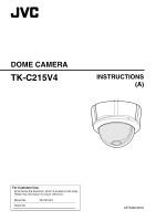
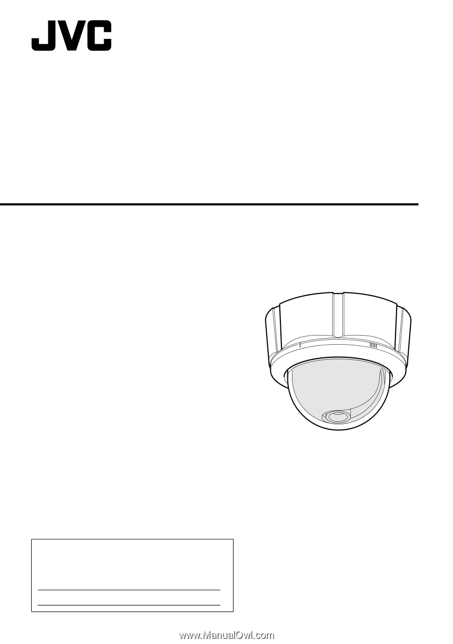
DOME CAMERA TK-C215V4 INSTRUCTIONS (A) For Customer Use: Enter below the Serial No. which is located on the body. Retain this information for future reference. Model No. Serial No. TK-C215V4 LST0420-001A - JVC TK-C215V4U | Instructions - Page 2
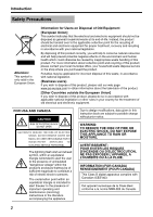
If you wish to dispose of this product, please visit our web page www.jvc-europe.com to obtain information about the take-back of the product. [Other maintenance (servicing) instructions in the literature accompanying the appliance. Due to design modifications, data given in this instruction book - JVC TK-C215V4U | Instructions - Page 3
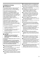
installation should be made by a qualified service person and should conform to all local 70. ⅷ Any Mention in this manual of Alarm inputs have not been JVC dealer for more details. ⅷ The ceiling to mount the camera has to be strong enough to support the installation instructions correctly. Please - JVC TK-C215V4U | Instructions - Page 4
service personnel under the following conditions: a. When the power cord or plug is damaged or frayed. b. If liquid has been spilled into the appliance. c. If the appliance has been exposed to rain or water. d. If the appliance does not operate normally by following the operating instructions - JVC TK-C215V4U | Instructions - Page 5
Thank you for purchasing this product. (These instructions are for: TK-C215V4U.) Before beginning to operate this unit, please read the instruction manual carefully in order to make sure that the best possible performance is obtained. Characteristics Ⅵ Realizing a High Picture Quality This camera - JVC TK-C215V4U | Instructions - Page 6
Introduction Contents Introduction Safety Precautions 2 Characteristics 5 Contents 6 Operating Precautions 7 Name of Parts 8 Camera 8 Camera (Interior 9 Setting the Lens and Switches 10 Installation and connection About Connection Cables 12 Video signal cables 12 DC 12 V or AC 24 V power - JVC TK-C215V4U | Instructions - Page 7
malfunction as a result. In this case, turn on the power after waiting for a few hours. ⅷ This unit enlarges the rotation angle to support wide range set up. For TK-C215V4 , when the zoom of the lens is set to WIDE end and the tilt angle is set around ±80Њ,the dome cover - JVC TK-C215V4U | Instructions - Page 8
Introduction Name of Parts Camera A B I H G B F C D A Mounting hole (elliptical) x 4 Use these when mounting the camera to the electrical box. (A pg. 18) NOTE: When installing the camera onto the electric box, install it using the supplied adaptor ring. B Mounting hole (round) x 4 Use these when - JVC TK-C215V4U | Instructions - Page 9
Camera (Interior) The dome cover, inner dome and outer case are removed. Procedures for removal. (A pg. 14 AEmbedding the camera to the ceilingB, Step 3. to Step 5.) V Lens (A Next page) J U Camera Unit (Rear) W T S O R Q K L P O M N J Strap A plate to connect the camera unit and the - JVC TK-C215V4U | Instructions - Page 10
to SPOT: When this button is pressed, white spots are corrected. For instructions on correcting white spots, see AWhite-spot correctionB (A pg. 21). B [R/B, +/-] R/B, +/- adjustment button This button is pressed when manually adjusting the white balance or when adjusting the vertical phase of the - JVC TK-C215V4U | Instructions - Page 11
selection switch. For selecting whether to adjust the white balance automatically or manually. When the setting is changed from manual to ATW, the setting values in the manual mode will be reset. The camera switches to the same mode as with pressing the [RESET] button. (Default setting: ATW) NOTE - JVC TK-C215V4U | Instructions - Page 12
Installation and connection About Connection Cables The maximum connection distance varies with the type of cable used. Please refer carefully to the table for each cable during connection. * Be sure to turn off the power of devices before connecting cables. To video Signal Cable To DC 12 V or AC - JVC TK-C215V4U | Instructions - Page 13
before installing the camera. ● Please refer to the instruction manual for the cover in use for details on installation of the embedded cover (recess bracket). ● For detail related to embedded cover (recess bracket), please contact JVC - JVC TK-C215V4U | Instructions - Page 14
Installation and connection Mounting the Camera (continued) Embedding the camera to the ceiling * Make use of a ceiling material with a thickness between 9.5 mm to 22 mm. Ⅵ Setup 1. Open a hole in the ceiling. (R120 mm, 4 3/4 inches) 2. Draw the fall prevention wire mounted to the ceiling slab - JVC TK-C215V4U | Instructions - Page 15
Ⅵ Connecting 1. Attach the fall prevention wire to the camera, followed by attaching it to the ceiling slab (Fall prevention wire is not included.) 2. Connect the video signal cable. (A pg. 12) Lower the cover and connect the connectors. Upon connecting, cover the connectors using the protection - JVC TK-C215V4U | Instructions - Page 16
Installation and connection Mounting the Camera (continued) When mounting the camera directly to the ceiling or on the wall When mounting to a wall, replace areas indicated as "ceiling" in the procedures by "wall". Ⅵ Setup 1. Open a hole in the ceiling. (R 30 mm, 1 1/8 inches) Make use of the - JVC TK-C215V4U | Instructions - Page 17
UPFRONT 1. Fall prevention wire (not supplied) Attach from the ceiling slab 3. Outer case mounting screws Less than 4 mm 2. Ⅵ Mounting 1. Align the position mark of the fastened outer case with that of the camera unit. NOTE: When doing so, be careful not to catch the cables in the outer case. - JVC TK-C215V4U | Instructions - Page 18
electrical box. Mount by allowing the cable to exit from the side When mounting the camera to the ceiling or a wall, it is possible to guide the cable from the side without opening any holes. The basic mounting method is identical to steps in AWhen mounting the camera directly to the - JVC TK-C215V4U | Instructions - Page 19
LENGTH 4 WHT. BAL. ATW AWB O N 4 FOCUS ADJUST 5 BLC OFF ON 6 DAY/NIGHT OFF ON 7 SHUTTER 1 /60 1 /100 8 RESEVED SET TO OFF SEE INSTRUCTION MANUAL Pan fastening screw : Be sure to loosen the screw before adjusting. Rotation knob : Always adjust the rotation by holding this knob. NOTE: ● Pan - JVC TK-C215V4U | Instructions - Page 20
Adjusting Image Adjusting Images (continued) Adjusting the field angle/focus/ brightness Upon determining the imaging direction, adjust the field angle, focus and iris level accordingly. The method of adjustment varies with the camera in use. L H IRIS LEVEL FOCUS ADJUST Iris Level Adjustment - JVC TK-C215V4U | Instructions - Page 21
Mounting the Inner Dome After setting is complete, mount the Inner dome. Claws (3 locations) White-spot correction As a general characteristic unique to CCDs, white-spots may appear on the screen with age. In order to reduce this phenomenon, this unit is equipped with a white-spot correction - JVC TK-C215V4U | Instructions - Page 22
ON, 50%) 0.4 lx (F1.3 AGC ON, 25%) White balance:ATW/Manual (Switchable) Color temperature range 2,300 K to 10,000 K Backlight compensation 40 f) (Recommended) Mass : Approx. 600 g Accessories Instructions 1 Warranty Card 1 Service Information Card 1 Template 1 Ⅵ External Dimensions [Unit: - JVC TK-C215V4U | Instructions - Page 23
Focus chart 23 - JVC TK-C215V4U | Instructions - Page 24
© 2006 Victor Company of Japan, Limited LST0420-001A TK-C215V4 DOME CAMERA
-
 1
1 -
 2
2 -
 3
3 -
 4
4 -
 5
5 -
 6
6 -
 7
7 -
8
-
9
-
10
-
11
-
12
-
13
-
14
-
15
-
16
-
17
-
18
-
19
-
20
-
21
-
22
-
23
-
24
 |
 |
DOME CAMERA
TK-C215V4
INSTRUCTIONS
(A)
For Customer Use:
Enter below the Serial No. which is located on the body.
Retain this information for future reference.
Model No.
TK-C215V4
Serial No.
LST0420-001A