Kenmore 3050 Installation Instructions
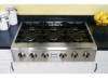
Kenmore 3050 - Pro 36 in. Gas Slide-In Cooktop Manual
 |
View all Kenmore 3050 manuals
Add to My Manuals
Save this manual to your list of manuals |
Kenmore 3050 manual content summary:
- Kenmore 3050 | Installation Instructions - Page 1
neighbor's phone. Follow the gas supp[ier's instructions. ,, ff you cannot reach your gas supplier, ca[[ the fire department. -- Installation and servke must be performed by a qualified installer, servke agency or the gas supplier. For Standard Installation: Gas Cooktop Dimensions /A * 30" (76 - Kenmore 3050 | Installation Instructions - Page 2
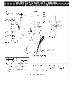
. H 7Y4"(18.4 cm) Gas Cooktop Cutout Dimensicns Do not sJide unit into cabinet cutout, Protruding screws on the bottom of unit may damage the bottom front finish. 351/_ cm/ Figure 2 **Note: D & E are critical to the proper installation of the cooktop. D reflects the finished dimension. Due - Kenmore 3050 | Installation Instructions - Page 3
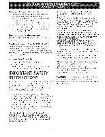
with any appliance using gas and generating heat, there are certain safety precautions you should follow. You will find them in the Use and Care Guide, read it carefully. Be sure your cooktop is installed and grounded properly by a qualified technician. installer or service • This cooktop must - Kenmore 3050 | Installation Instructions - Page 4
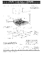
risk of burns or fire from reaching over heated surfaces, cabinet storage space located above tile cooktop should be avoided. If cabinet storage is provided, risk can be reduced by installing a range hood that projects horizontally a minimum of 7" (17.8 cm) beyond tile bottom of the cabinets. It - Kenmore 3050 | Installation Instructions - Page 5
from the factory for use with natural gas. A kit for converting to LP gas is supplied with your cooktop. The kit is marked "FOR LP/PROPANEGAS CONVERSION". The conversion must be performed by a qualified service technician in accordan(e with the kit instructions and all local codes and requirements - Kenmore 3050 | Installation Instructions - Page 6
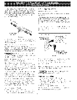
before servicing cooktop. Cooktop Installation 1. Visually inspect the cooktop for damage. 2. If you are installing the optional Stainless Steel backsplash, first fix it at the back of the cooktop using the screws supplied with the kit and follow the instructions attached. 3. Set the cooktop into - Kenmore 3050 | Installation Instructions - Page 7
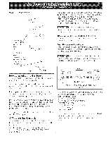
Check Operation Refer to tile Use and Care Guide packaged with the cooktop for operating instructions and for care and cleaning of your cooktop. Do not touch the burners, They may be hot enough to cause burns, tnstaI] Burner Caps This cooktop is equipped with sealed burners as shown (see Figure 8). - Kenmore 3050 | Installation Instructions - Page 8
of the burners, tile type of fuel and the pressure the cooktop was adjusted for when it left tile factory. Before You Call for Service Read the Before You Call for Service Checklist and operating instructions in your Use and Care Guide. It may save you time and expense. The list includes common - Kenmore 3050 | Installation Instructions - Page 9
Notes: - Kenmore 3050 | Installation Instructions - Page 10
Notes: 10 - Kenmore 3050 | Installation Instructions - Page 11
t_[_fonico deben serreaJizadospot un insta[ador caHficado,pot un servic[otecn[co certffkado o pot el abastecedor de gas. Para [a Insta[adOn Est_indar: * 30" (76,2 inferior de [a unidad pueden acabado inferior de[ frente. de la parte daffar el FJgura 1 **Nota: "D & E" son criticos para - Kenmore 3050 | Installation Instructions - Page 12
) rain para una superficie no protegida. Dimensiones de la parrilla de cocinar a gas 30"(76.2 cm) Min.* Panel Protector Opcional de Acero Inoxidable de -- 9" Panel Protector. C Abertura de 4" X 4" para el suministro de gas. Abertura de 2" (5.1cm) de diametro para pasar el cable de alimentaci6n - Kenmore 3050 | Installation Instructions - Page 13
Centro de Partes y Reparacion Installation, ANS!/NCSBCS 225.1, o con los codigos locales. El diseflo de esta plancha de cocinar cuenta con la aprobaci6n del CSA international. AI igual que todos los artefactos a gas que generan calor, deben seguirse ciertas medidas de seguridad. Vienen con el Manual - Kenmore 3050 | Installation Instructions - Page 14
posterior del \ hueco y lamas cerca _'_ superficie combustible por encima del mostrador. / 18" (45.7 cm) M[n. 30" (76.2 cm) M[nimo de espacio entre la parte superior de la plataforma de la plancha de co(inar y el fondo de una madera non protegida o armario metalico. T!_ Para eliminar el riesgo - Kenmore 3050 | Installation Instructions - Page 15
de realizar las conexiones de gas y el6ctricas a la cocina. Instaiaci6n de[ reguiador de presi6n Instale el regulador de presi6n (:on del suministro de gas al regulador de presi6n en funcionamiento: 1. vdvula de cierre manual 2. boquilla de 1/2" (! .3 cm) La I[nea de suministro de gas pot el homo - Kenmore 3050 | Installation Instructions - Page 16
el Panel Protector Optional de Acero Inoxidable, primero coloquelo en la parte posterior de la tapa de la cocina usando los tornillos provistos con suministro de gas cierrando su valvula de cierre individual manual, durante cualquier ensayo de presi6n del systema de suministro de gas en ensayos - Kenmore 3050 | Installation Instructions - Page 17
de tas vSJvuJas de superficie de quemador (vet Figura 9) interiormente elevado en las partes inferiores del Presione y gire el botOn de control al ajuste "LO" (o lado Superficie de la plancha de cocinal Base del quemador Abertura del gas Figura 8 A. Deje que la cocina se enfrle a temperatura - Kenmore 3050 | Installation Instructions - Page 18
letra del Iote que se encuentran en la plata, en todo pedido de partes o solicitud de informaci6n acerca de su plancha de cocinar. La placa de "Evitando Llamadas de Servicio" y las instrucciones de funcionamiento en su Manual del Usuario Verifique que los fusibles de la casa no se hayan fundido - Kenmore 3050 | Installation Instructions - Page 19
Notas: 19 - Kenmore 3050 | Installation Instructions - Page 20
j BK I 1ONBd INT ENC DE CENTRO iZOU]B_ Jd _ I ENN_ETRER _LFLRUOMNT CENTRE AV_NT CAU r I ON : L] I_ _LL /dtREB PROR TD DISCONNECTION _/HEN SERVICING CONTRD! 5 _'[RING ERROR CAN DR,USE iI'_P4OPER AND D_NG_ROLJS OPERATION VER I FY PROPER OPERAT [ ON AFTER 5ERV I C I NG ETIOUETE REAL IZAR
-
 1
1 -
 2
2 -
 3
3 -
 4
4 -
 5
5 -
 6
6 -
 7
7 -
8
-
9
-
10
-
11
-
12
-
13
-
14
-
15
-
16
-
17
-
18
-
19
-
20
 |
 |
INSTALLATION
AND
SERVICE MUST
BE PERFORMED
BY
A QUAUHED
INSTALLER.
IMPORTANT:
SAVE
FOR LOCAL ELECTRICAL
INSPECTOR'S
USE.
READ AND
SAVE
THESE INSTRUCTIONS
FOR FUTURE
REFERENCE.
[f the information
in this manual
is not followed
exactly,
a fire
or explosion
may result
causing
property
damage,
personal
injury
or death.
FOR YOUR SAFETY:
--
Do not store
or use gasoline
or other
flammabJe
vapors
and liquids
in the vMnity
of this
or any other
appliance.
--
WHAT TO DO tF YOU SMELL GAS:
*
Do not try to light
any appliance.
Do not touch
any
e[ectrka[
switch;
do not use any phone
in your
building,
Immediately
call
your
gas supplier
from
a neighbor's
phone.
Follow
the gas supp[ier's
instructions.
,,
ff you cannot
reach your
gas supplier,
ca[[ the fire
department.
--
Installation
and servke
must
be performed
by a qualified
installer,
servke
agency
or the gas supplier.
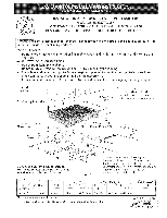
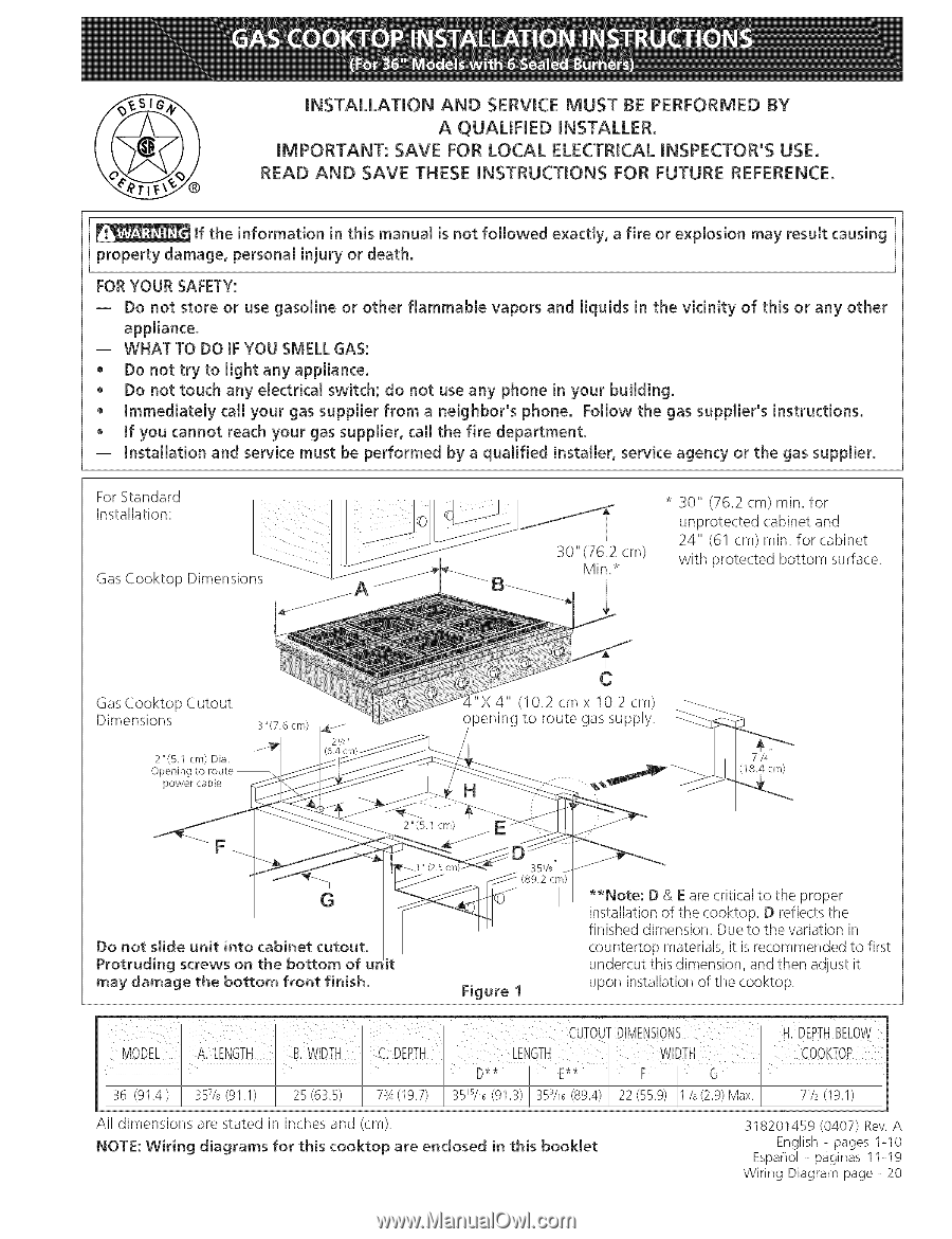
For Standard
Installation:
Gas Cooktop Dimensions
Gas Cooktop Cutout
Dimensions
/A
2"(5.1
cm) Dia.
Opening
to route --
power
cabFe
*
30"
(76.2 cm) rain. for
unprotected cabinet and
24" (61 cm) rain. for cabinet
with protected bottom surface.
X4"
(!0.2
cm x 10.2 cm)
opening to route gas supply.
71/4
(18.4 cm)
F
G
Do not slide unit
into
cabinet cutout,
Protruding
screws
on the bottom
of ur it
may damage
the bottom
front
finish.
Figure
1
**Note:
D & Eare critical to the proper
installation of the cooktop. D reflects the
finished dimension. Due to the variation in
countertop materials, it is recommended to first
undercut this dimension, and then adjust it
upon installation of the cooktop.
All dimensions are stated in inches and (cm).
NOTE: Wiring
diagrams
for
this cooktop
are enclosed
in this booklet
318201459
(0407)
Rev A
English
- pages
1o10
Espar_ol
-
Diginas
11-19
Wiring
Diagram
page
- 20