Kenmore 3050 Installation Instructions - Page 6
isfor turningonor
 |
View all Kenmore 3050 manuals
Add to My Manuals
Save this manual to your list of manuals |
Page 6 highlights
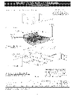
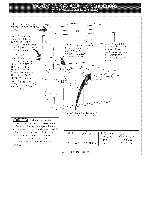
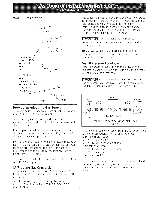
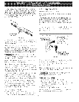
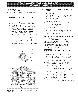
Thesupplylineshouldbeequippedwithanapproved shutoffvalveT. hisvalveshouldbelocatedinthe same roomasthecooktopandshouldbeina locationthat allowseaseof openingandclosingD. onot blockaccess to theshutoffvalveT. ilevalveisfor turningonor shuttingoff gasto theappliance. Grounding Instructions IMPORTANT Please read carefully. For personal safety, this appliance must be properly grounded. The power cord of this appliance is equipped with a 3prong (grounding) plug which mates with a standard 3prong grounding wall receptacle (see Figure 7) to minimize the possibility of electric shock hazard from the appliance. The wall receptacle and circuit should be checked by a qualified electrician to make sure the receptacle is properly grounded. Shutoff Valve Open position Figure 6 Once the regulator is in place, open the shutoff valve in the gas supply line. Wait a few minutes for gas to move through tile gas line. Check for leaks. After connecting the cooktop to the gas supply, check the system for leaks with a manometer. If a manometer is not available, turn on the gas supply and use a liquid leak detector (or soap and water) at all joints and connections to check for leaks. Do not use a flame to check for leaks from gas connections. Checking for leaks with a flame may result in a fire or explosion. Tighten all connections if necessary to prevent gas leakage in the cooktop or supply line. Check alignment of control knob valves after connecting the cooktop to the gas supply to be sure the cooktop manifold pipe has not moved. A misalignment could cause the valve stems to rub on the control panel, resulting in a gas leak at tile valve. Disconnect this cooktop and its individual shutoff valve from the gas supply piping system during any pressure testing of that system at test pressures greater than 1/2 psig (3.5 kPa or 14" (35.6 cm) water column). tsotate the cooktop from the gas supply piping system by (:losing its individual manual shutoff valve during any pressure testing of the gas supply piping system at test pressures equal to or less than 1/2 psig (3.5 kPa or 14" (35.6 cm) water column). Electrical Requirements 120 volt, 60 Hertz, properly grounded branch circuit protected by a 15 amp circuit breaker or time delay fuse. Do not use an extension cord with this cooktop. Preferred Method f Grounding type wall receptacle / ( cord with 3-prong grounding plug, Figure 7 Where a standard 2-prong wall receptacle is installed, it is the personal responsibility and obligation of the consumer to have it replaced by a properly grounded 3prong wall receptacle. Do not, under any circumstances, cut or remove the third (ground) prong from the power cord. Disconnect electrical supply cord from wall receptacle before servicing cooktop. Cooktop Installation 1. Visually inspect the cooktop for damage. 2. If you are installing the optional Stainless Steel backsplash, first fix it at the back of the cooktop using the screws supplied with the kit and follow the instructions attached. 3. Set the cooktop into the countertop cutout. NOTE: Do not use caulking compound; cooktop should be removable for service when needed.
-
 1
1 -
 2
2 -
 3
3 -
 4
4 -
 5
5 -
 6
6 -
 7
7 -
 8
8 -
 9
9 -
 10
10 -
 11
11 -
 12
12 -
13
-
14
-
15
-
16
-
17
-
18
-
19
-
20
 |
 |
