KitchenAid KUID508HPS Installation Instructions - Page 10
Parts Locations, Vent Tube, NOTES, Drain Tube
 |
View all KitchenAid KUID508HPS manuals
Add to My Manuals
Save this manual to your list of manuals |
Page 10 highlights
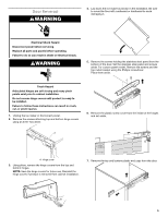
5. Align the 2 screw holes at the rear of the pump. Use two #8-32 x 3/8" screws, supplied. See "Parts Locations" illustration. 6. Install vent tube (5/16" I.D. x 32" [81 cm]) to drain pump reservoir vent behind the wiring cover. Use supplied 5/8" small adjustable clamps. See "Parts Locations" illustration. Use plastic retainer to keep vent hose secure to top of inner deck. NOTE: Do not install household drain tube this time. Parts Locations Vent Tube NOTE: Do not pinch, kink or damage the vent tube. Check that it is not damaged or pinched or kinked between the cabinet and the ice maker. A B C I H C G E F A. Vent tube B. 5/8" hose clamp C. Drain pump discharge tube D. Drain pump E. Ice maker unit power cord D BA F. #8-32 x 3/8" pump mounting screws G. Drain pump power cord, clamp and screw H. Plastic retainer I. Wiring cover 7. Remove wiring cover. Refer following illustration for location of the screws. A B A. Vent tube B. Cable ties C. Plastic retainer 9. Secure wiring cover back in place. 10. Remove power cord clamp and ground screw attached to ice maker power cord, which is mounted to the unit base. See "Parts Locations" illustration. NOTE: Clamp and screw will be reused. 11. Coil ice maker power cord into a 4" (10.2 cm) diameter coil. Wrap electrical tape around the power cord in several places to keep the cord in a coil. Locate coiled power cord between the drain pump and side of enclosure and plug into the receptacle of the drain pump. See "Parts Locations" illustration. 12. Attach the drain pump power cord to ice maker unit base with clamp and screw (removed in Step 6) that was used to attach ice maker power cord. See "Parts Locations" illustration. 13. Install new drain tube (5/8" I.D. x 5¹⁄8") from ice maker bin to drain pump reservoir inlet using new adjustable clamps. See "Drain Tube" illustration. NOTES: ■■ Do not kink. ■■ Trim tube length if required. Drain Tube A B A. Wiring cover B. Screws 8. Route vent tube through plastic retainer that is located underneath top deck in open pump area as shown in illustration. Using cable tie, tie the vent tube to the black suction tube which is located behind the wiring cover. Refer "Vent Tube" illustration. C D A. 7/8" adjustable hose clamp C. 7/8" adjustable hose clamp B. Drain tube (ice bin to drain pump) D. Drain pump reservoir inlet 10
-
 1
1 -
2
-
3
-
4
-
 5
5 -
 6
6 -
 7
7 -
 8
8 -
 9
9 -
 10
10 -
 11
11 -
 12
12 -
 13
13 -
 14
14 -
 15
15 -
16
-
17
-
18
-
19
-
20
-
21
-
22
-
23
-
24
-
25
-
26
-
27
-
28
-
29
-
30
-
31
-
32
-
33
-
34
-
35
-
36
-
37
-
38
-
39
-
40
-
41
-
42
-
43
-
44
-
45
-
46
-
47
-
48
-
49
-
50
-
51
-
52
-
53
-
54
-
55
-
56
 |
 |
