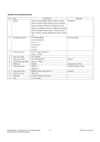
LG 50PW450 Service Manual - Page 8
Function Check, Total Assembly line process - tv
 |
View all LG 50PW450 manuals
Add to My Manuals
Save this manual to your list of manuals |
Page 8 highlights
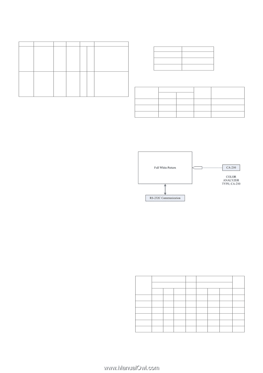
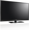
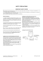
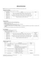
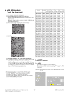
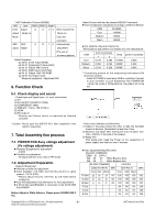
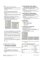
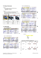
* ADC Calibration Protocol (RS232) NO Item CMD 1 CMD 2 Data 0 Enter Adjust A A 0 0 When transfer the Adjust rMode Ins rMode Ins Mode Carry the command. ADC ADC A D 1 0 Automatically adjust Adjust adjustment (The use of a internal pattern) Adjust Sequence - aa 00 00 [Enter Adjust Mode] - xb 00 40 [Component1 Input (480i)] - ad 00 10 [Adjust 480i Comp1] - xb 00 60 [RGB Input (1024*768)] - ad 00 10 [Adjust 1024*768 RGB] - aa 00 90 End Adjust mode * Required equipment : Adjustment R/C. 6. Function Check Adjust Process will start by execute RS232C Command. O Color temperature standards according to CSM and Module CSM PLASMA Cool 11000K Medium 9300K Warm 6500K O CS-1000/CA-100+/CA-210(CH 10) White balance adjustment coordinates and color temperature. CSM Color Coordinate x y Temp ±Color Coordinate Cool 0.276 0.283 11000K 0.002 Medium 0.285 0.293 9300K 0.002 Warm 0.313 0.329 6500K 0.002 * Connecting picture of the measuring instrument (On Automatic control) - Inside PATTERN is used when W/B is controlled. Connect to auto controller or push Adjustment R/C POWER-ON ->Enter the mode of White-Balance, the pattern will come out. 6-1. Check display and sound - Check Input and Signal items. (cf. work instructions) (1) TV (2) AV (SCART1/SCART2/ CVBS) (3) COMPONENT (480i) (4) RGB (PC : 1024 x 768 @ 60hz) (5) HDMI (6) PC Audio In * Display and Sound check is executed by Remote controller. * Caution : Not to push the INSTOP KEY after completion if the function inspection. 7. Total Assembly line process 7-1. POWER PCB Assy voltage adjustment (Vs voltage adjustment) O Required Equipment for adjustment - D.M.M O Condition for adjustment - No signal with the snow noise in RF mode) 7-2. Adjustment Preparation - Required Equipment O Remote controller for adjustment O Color Analyzer ( CS-1000, CA-100,100+,CA-210 or same product : CH 10 (PDP) * Please adjust CA-210, CA-100+ by CS-1000 before measuring O Auto W/B adjustment instrument(only for Auto adjustment) O 9 Pin D-Sub Jack(RS232C) is connected to the AUTO W/B EQUIPMENT. Before Adjust of White Balance, Please press POWER ONLY key * Auto-control interface and directions (1) Adjust in the place where the influx of light like floodlight around is blocked. (Illumination is less than 10ux). (2) Measure and adjust after sticking the Color Analyzer (CA- 100+, CA210 ) to the side of the module. (3) Aging time After aging start, keep the Power on (no suspension of power supply) and heat-run over 5 minutes O Auto adjustment Map(RS-232C) RS-232C COMMAND [ CMD ID DATA ] Wb 00 00 White Balance Start Wb 00 ff White Balance End RS-232C COMMAND CENTER [CMD ID DATA] MIN (DEFAULT) MAX Cool Mid Warm Cool Mid Warm R Gain jg Ja jd 00 192 192 192 192 G Gain jh Jb je 00 192 192 192 192 B Gain ji Jc jf 00 192 192 192 192 R Cut 64 64 64 128 G Cut 64 64 64 128 B Cut 64 64 64 128 Copyright ©2011 LG Electronics Inc. All rights reserved. Only for training and service purposes -8- LGE Internal Use Only
-
 1
1 -
2
-
 3
3 -
 4
4 -
 5
5 -
 6
6 -
 7
7 -
 8
8 -
 9
9 -
 10
10 -
 11
11 -
 12
12 -
 13
13 -
14
-
15
-
16
-
17
-
18
-
19
-
20
-
21
-
22
-
23
-
24
-
25
-
26
-
27
-
28
-
29
-
30
-
31
-
32
-
33
-
34
-
35
-
36
-
37
-
38
-
39
-
40
-
41
-
42
-
43
-
44
-
45
-
46
-
47
-
48
-
49
-
50
-
51
-
52
-
53
-
54
-
55
-
56
-
57
-
58
-
59
-
60
-
61
-
62
-
63
-
64
-
65
-
66
-
67
-
68
-
69
-
70
-
71
-
72
-
73
 |
 |