LG GR-J303TS Service Manual - Page 15
Explanation Of Circuits
 |
View all LG GR-J303TS manuals
Add to My Manuals
Save this manual to your list of manuals |
Page 15 highlights
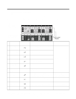
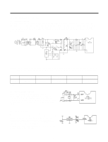
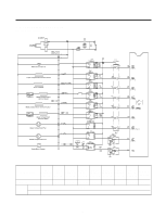
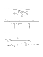
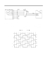
3-2. EXPLANATION OF CIRCUITS 3-2-1. POWER CIRCUIT Power circuits consist of SMPS (Switching Mode Power Supply) power, and the SMPS consists of the rectification part (BD1, CE1) to convert AC voltage to DC voltage, the switching part (IC3) to switch the converted DC voltage, a transformer to transfer energy of the primary side on the switching terminal, secondary side power to supply power to the MICOM and IC and the feed back part (IC4, IC5) to feedback the secondary side voltage to the primary side of transformer in order to maintain it uniformly. Caution.: Take a measure after more than 3 minutes have passed after removing the power cords in abnormal operation of circuits since high voltage (DC310V) is maintained at the power terminal. Otherwise, it may cause electric shock. Part Both ends of VA1 Both ends of CE1 Both ends of CE2 Voltage 220 Vac Voltage of each part is as follows: 310 Vdc 16 Vdc Both ends of CE3 Both ends of CE4 12.5 Vdc 5 Vdc 3-2-2. OSCILLATION CIRCUIT Oscillation circuits are intended to generate clock for synchronization for information transmission/receipt of logic elements inside of the IC1 (MICOM) and generate basic time for time calculation. Rated parts must be used since the OSC1 does not operate or time calculated at the IC1 changes where SPEC changes. 3-2-3. RESET CIRCUIT The reset circuits are intended so that the whole of function is started at the initial status by initializing various parts such as ram inside of the MICOM (IC1) when power is applied to MICOM again in input of initial power or by temporary power failure. "LOW" voltage is applied to the reset terminal of MICOM for the fixed time (10ms) at the start of power input. During general operation, the reset terminal is at 5V (No MICOM operates in case of poor reset IC). - 15 -
-
 1
1 -
2
-
3
-
4
-
5
-
6
-
7
-
8
-
9
-
 10
10 -
 11
11 -
 12
12 -
 13
13 -
 14
14 -
 15
15 -
 16
16 -
 17
17 -
 18
18 -
 19
19 -
 20
20 -
21
-
22
-
23
-
24
-
25
-
26
-
27
-
28
-
29
-
30
-
31
-
32
-
33
-
34
-
35
-
36
-
37
-
38
-
39
-
40
-
41
-
42
-
43
-
44
-
45
-
46
 |
 |
