LG GR-J303TS Service Manual - Page 20
ACCW reverse rotation BCW positive rotation
 |
View all LG GR-J303TS manuals
Add to My Manuals
Save this manual to your list of manuals |
Page 20 highlights
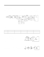
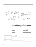
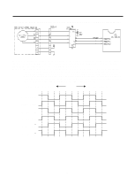
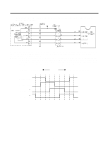
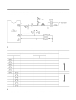
3-2-8. STEPPING MOTOR DAMPER DRIVE CIRCUIT (FOR TEMPERATURE CONTROL AT MIDDLE COMPARTMENT) As for motor drive, the motor rotates since rotation magnetic force is formed at coils wound around each phase of the motor and the stator if outputting "High" "Low" signal as much as the fixed step numbers through the MICOM pin 51 and pin 52 after applying "High" signal to the IC 12 (TA777AP) from the MICOM pin 53. Explanation) For driving method of the motor, send signal in the cycle of 3.33ms by using the terminal of the MICOM PIN53, 52 and 51 as shown in waveform of each part below. This signal is output to the output terminal No.10, 11, 14, 15 via the input terminal No.3, 6, 8 of the IC12 (TA7774P) as IC for motor drive. The motor rotates by which motor coils wound around each phase of the stator forms rotation magnetic field. The stepping motor damper rotates by which motor coils wound around each phase of the stator forms rotation magnetic field if inputting as figure to the input part (No.3 INA, No.6 INB) of the IC12 (TA7774P) for motor drive. CCW (reverse rotation) CW (positive rotation) IC12 No.3 (INA) IC12 No.6 (INB) IC12 No.15 (A) IC12 No.10 (B) IC12 No.14 (A) IC12 No.11 (B) - 20 -
-
 1
1 -
2
-
3
-
4
-
5
-
6
-
7
-
8
-
9
-
10
-
11
-
12
-
13
-
14
-
 15
15 -
 16
16 -
 17
17 -
 18
18 -
 19
19 -
 20
20 -
 21
21 -
 22
22 -
 23
23 -
 24
24 -
 25
25 -
26
-
27
-
28
-
29
-
30
-
31
-
32
-
33
-
34
-
35
-
36
-
37
-
38
-
39
-
40
-
41
-
42
-
43
-
44
-
45
-
46
 |
 |
